
Motor having stator with coupled teeth

a stator and motor technology, applied in the field of motors, can solve problems such as difficulty in maintaining the shape of the stator and the motor, and achieve the effect of increasing the counter electromotive force and output of the motor, and increasing the number of coils

Active Publication Date: 2020-04-14
NEW MOTECH +1
View PDF18 Cites 0 Cited by
  • Summary
  • Abstract
  • Description
  • Claims
  • Application Information

AI Technical Summary

Benefits of technology

[0016]The present invention provides a motor of a new structure which can fully utilize the vernier effect, thereby increasing the counter electromotive force and output of the motor, and increasing the number of coils even when the laminating height of the stator is not high enough.

Problems solved by technology

However, in the case of a motor with a slim shape whose stack height is not high enough, there would be a difficulty in maintaining the shapes of the stator and motor as the number of coils increases.

Method used


Image

  • Motor having stator with coupled teeth
  • Motor having stator with coupled teeth
  • Motor having stator with coupled teeth

Examples


Embodiment Construction

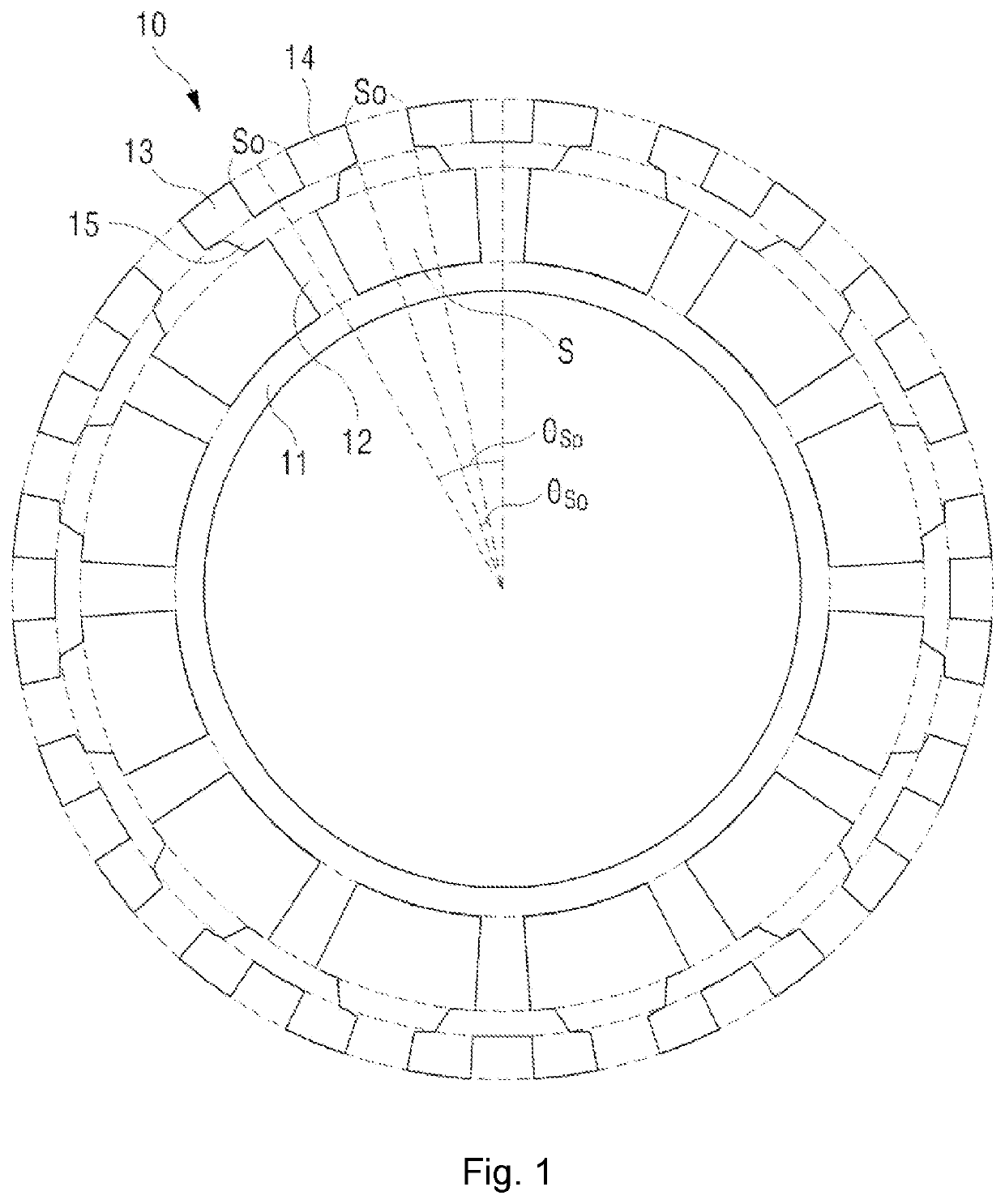
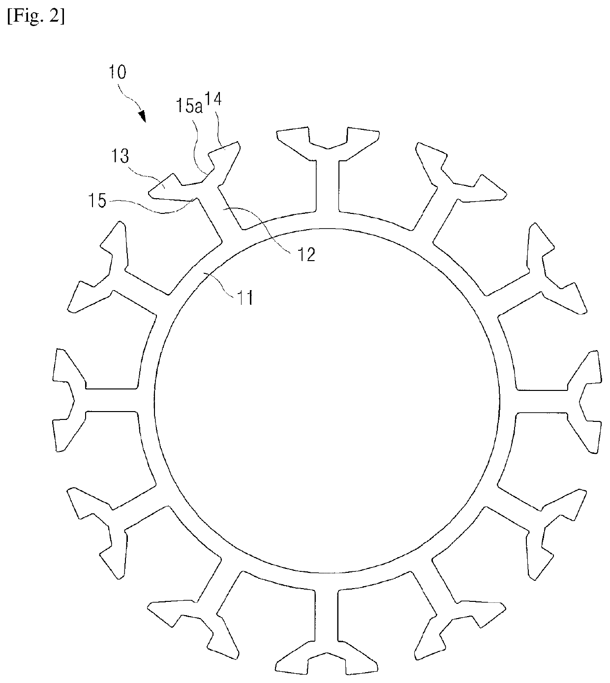
[0023]FIG. 1 is a plan view illustrating an embodiment of a stator 10 of a motor according to the present invention, and FIG. 2 is a plan view illustrating another embodiment of a stator of a motor according to the present invention

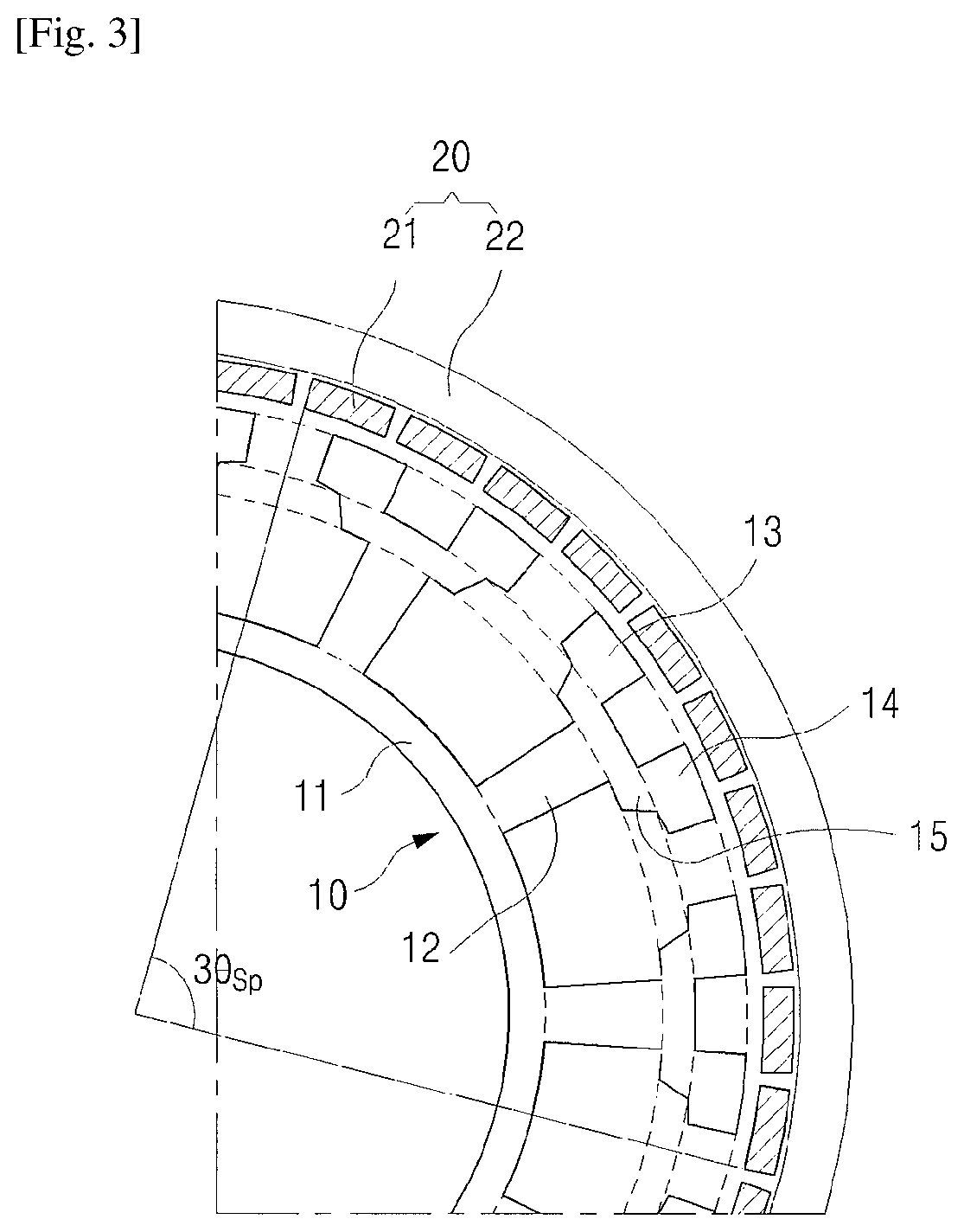
[0024]As illustrated in FIG. 1 and FIG. 2, a stator 10 of a motor according to the present invention includes a circular base 11, a plurality of poles 12 radially formed in the circular base 11, first and second teeth 13 and 14 with symmetrical shape at locations symmetrical to each other at the end of the pole, and a bridge 15 connecting the first and second teeth 13 and 14.

[0025]In general, a stator or a stator assembly includes a stator core manufactured by laminating a plurality of thin steel plates, an insulator which insulates a base, pole and teeth of the stator core, and a coil wound in the insulated pole. The term ‘a stator’ used herein may mean ‘a stator core’ or a case including the stator, insulator and coil. In the present specification, most...


PUM


Abstract

A motor having a stator with coupled teeth according to the present invention includes a stator which includes a circular base, a plurality of poles radially formed in the base, and a plurality of teeth formed on an outer diameter of the pole; and a rotor which includes a rotor housing in which the stator is positioned inside and a plurality of magnets facing the teeth are formed on an inner wall, wherein two teeth are symmetrically formed on an outer diameter portion for each pole, and the number of teeth is twice the number of poles.

Description

TECHNICAL FIELD[0001]The present invention relates to a motor. More specifically, the present invention relates to a motor which includes a stator with a structure capable of increasing counter electromotive force and the number of coils in the stator by fully obtaining a vernier effect.BACKGROUND ART[0002]Vernier reluctance motors have been known for about 50 years, and a concept of vernier permanent magnet motors was suggested about 20 years ago. According to the recent research, it is reported that the vernier permanent magnet motors may obtain an output increase of a motor by the increase of counter electromotive force when considering air-gap permeance between teeth of a stator and a magnet of a rotor (Byungtaek Kim et al., “Operation and Design Principles of a PM Vernier Motor”, IEEE Transactions on Industry Applications, Vol. 50, No. 6, pp. 3656-3662).[0003]In order to increase the counter electromotive force, it is necessary to make a change of magnetic flux density accordin...

Claims


Application Information

Patent Timeline
Patent Type & Authority Patents(United States)
IPC IPC(8): H02K1/16H02K1/27H02K21/22H02K21/14
CPCH02K1/165H02K1/2786H02K21/22H02K21/14H02K2213/03H02K1/2791
Inventor JANG, JEONG CHEOLLEE, JI MINYANG, GYEONG SIKLEE, SEUNG HOONKIM, BYUNG TAEKKIM, NAM JONG
Owner NEW MOTECH
Learn More