Bumper beam

a bumper beam and beam technology, applied in the field of bumper beams, can solve the problems of increasing tooling costs and complex current bumper beam designs, and achieve the effect of preventing cracking and being adaptable and flexibl

Active Publication Date: 2020-04-28
MAGNA INTERNATIONAL INC
View PDF46 Cites 10 Cited by
  • Summary
  • Abstract
  • Description
  • Claims
  • Application Information

AI Technical Summary

Benefits of technology

[0009]The geometrical features of the bumper beam can be varied in size and shape to change and tune the energy absorption properties of the bumper beam and ultimately provide for a bumper beam that is more adaptable and flexible over a range of different vehicle segments when compared to prior art bumper beams. In addition, the geometrical features provide for a bumper beam that includes a unique cross-sectional or design geometry that permits for a lighter weight bumper beam as compared to previous designs and distributes energy from an impact to prevent cracking of the bumper beam.

Problems solved by technology

There are several issues with current bumper beam designs and methods of manufacture.
In addition, current bumper beam designs are generally quite complex and incorporate a plurality of cross-ribs and other support structures in the bumper beam to meet the necessary performance and regulatory requirements.
Such designs require complex tooling to manufacture the bumper beam which can add to tooling costs associated with changing the bumper beam designs to match and accommodate changes in the vehicle market segment designs.

Method used


Image

  • Bumper beam
  • Bumper beam
  • Bumper beam

Examples


Embodiment Construction

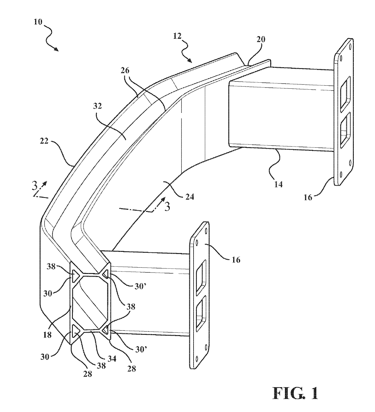
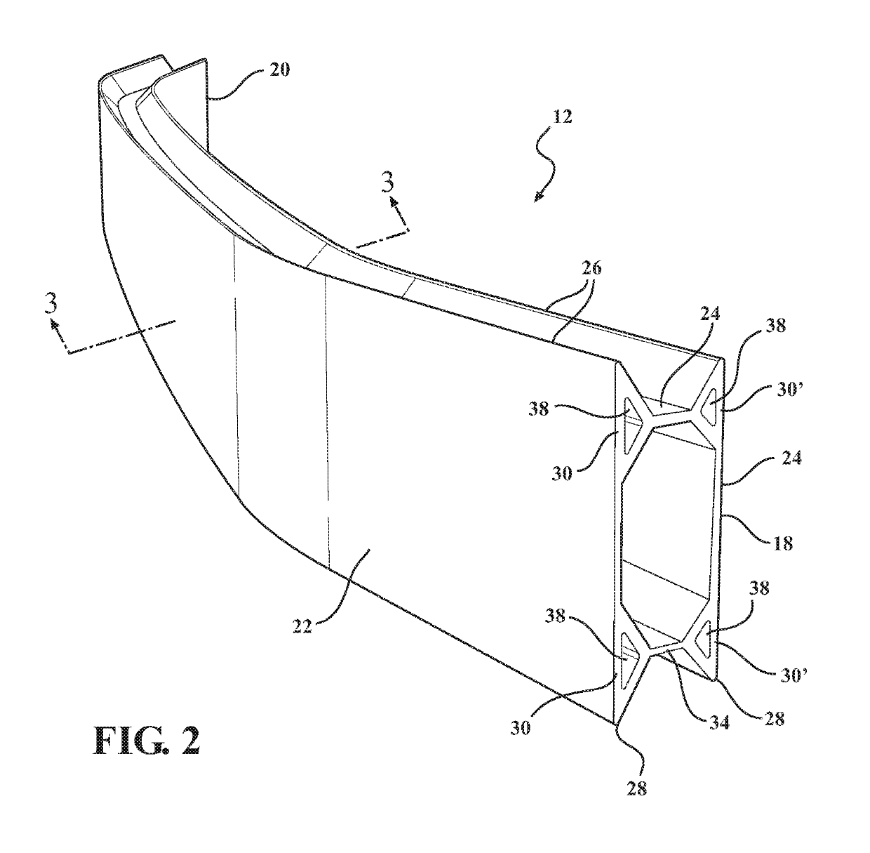
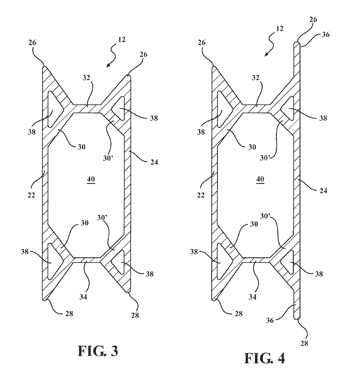
[0023]As discussed herein, it is desirable to create a bumper beam having a lighter weight that can be rapidly tuned during design to accommodate a variety of vehicle segments in a cost efficient manner. The current vehicle bumper beam designs often include an outer wall and an inner wall joined by a top wall and a bottom wall and other complex structures or connecting features. Such structures are difficult to modify and to design the tooling for manufacturing the bumper beam. The present disclosure is directed to a more universal bumper beam design that can be easily modified to fit across a variety of vehicle segments.

[0024]As best illustrated in FIGS. 1 and 11, a bumper assembly 10 can include a bumper beam 12 as well as a pair of crush cans 14 that can be used to secure the bumper assembly 10 to a frame member of a vehicle. However, as best illustrated in FIGS. 2 and 12, the bumper assembly 10 can also include only the bumper beam 12 which is then secured directly to the vehicl...


PUM


Abstract

A bumper beam includes an outer portion and an inner portion each extending between a top end and a bottom end. At least one of the outer portion or the inner portion includes a pair of geometrical features each of which are disposed in spaced relationship to one another and adjacent a respective one of the top or bottom ends. A top wall and a bottom wall each extend from one of the geometrical features to the other of the outer portion or the inner portion to interconnect the outer and inner portions of the bumper beam. The geometrical features can be varied in size and shape to change and tune the energy absorption properties of the bumper beam and ultimately provide for a bumper beam that is adaptable and flexible over a range of vehicle applications.

Description

CROSS REFERENCE TO RELATED APPLICATIONS[0001]This U.S. National Stage Patent Application claims the benefit of PCT Patent International Application Serial No. PCT / US2016 / 043373 filed Jul. 21, 2016 entitled “Bumper Beam” which claims the benefit of U.S. Provisional Patent Application Ser. No. 62 / 194,960 filed on Jul. 21, 2015 entitled “Bumper Beam,” the entire disclosures of the applications being considered part of the disclosure of this application and hereby incorporated by reference.STATEMENT REGARDING FEDERALLY SPONSORED RESEARCH[0002]NONE.TECHNICAL FIELD[0003]This invention relates generally to a vehicle bumper assembly and more particularly to a bumper beam for a vehicle.BACKGROUND OF THE INVENTION[0004]Vehicle bumper assemblies are known for providing energy absorbing characteristics. A typical vehicle bumper assembly comprises a bumper beam and a pair of crush cans. The crush cans are positioned on the end of a frame member of a vehicle body structure and also secured to the...

Claims


Application Information

Patent Timeline
Patent Type & Authority Patents(United States)
IPC IPC(8): B60R19/02B60R19/18
CPCB60R19/18B60R2019/1806B60R2019/182
Inventor JADHAV, AMAR RAJENDRAYALDO, JOSEPH MATTHEWGUJJAL, SHRIKANTHCAITO, JOHN J.MELLIS, JEFFREY
Owner MAGNA INTERNATIONAL INC
Why Eureka
Try Eureka