
Lubrication of scroll compressor

a compressor and scroll technology, applied in the direction of machines/engines, rotary/oscillating piston pump components, liquid fuel engines, etc., can solve the problems of hardly making the oil circulation rate within an appropriate range, bringing stability and reliability, etc., to achieve effective prevention of oil circulation rate, increase oil circulation rate, and avoid excessive high oil circulation rate

Active Publication Date: 2020-05-05
EMERSON CLIMATE TECH (SUZHOU) CO LTD
View PDF86 Cites 3 Cited by
  • Summary
  • Abstract
  • Description
  • Claims
  • Application Information

AI Technical Summary

Benefits of technology

[0011]Another object of the present application is to provide a scroll compressor having a compression mechanism oil supply device capable of effectively preventing an oil circulation rate from significantly exceeding an upper limit of a desired range at a low evaporation temperature / low compressor rotational speed.
[0012]Another object of the present application is to provide a scroll compressor having a compression mechanism oil supply device capable of sufficiently improving the adjustment accuracy and design freedom of the oil circulation rate.
[0015]Specifically, on the one hand, for example, in the case of a low rotational speed condition, it is possible to increase an oil circulation rate to make it within a desired range as compared with a solution in which an active oil injection mechanism for supplying oil to the compression mechanism is not provided. On the other hand, for example, in the case of a high rotational speed condition, the oil circulation rate will not be excessively increased (basically the oil circulation rate may be only slightly increased) and may be kept within a desired range (for example, this is because at a high rotational speed, the mass of the lubricant expelled out of the orbiting scroll base plate is relatively small at each revolution of the compression mechanism). Thereby, the oil circulation rate can be made within an appropriate range at different compressor rotational speeds and / or under different system operation parameters. In particular, it is possible to effectively prevent the oil circulation rate from significantly exceeding an upper limit of the desired range at a low evaporation temperature / low compressor rotational speed. Therefore, it is possible to avoid an excessively high oil circulation rate which causes the lubricant to accumulate around the discharge valve assembly and brings stability and reliability issues to the scroll compressor.
[0016]In addition, according to the present application, a counterbore having a larger inner diameter is provided, an outlet hole is provided and / or a plug having a through hole with a smaller inner diameter is provided, thus, the adjustment accuracy and design freedom of the oil circulation rate can be sufficiently improved, thereby enabling the compression mechanism oil supply device to have a more excellent versatility and applicability.

Problems solved by technology

Accordingly, the compression mechanism oil supply device CO′ according to the related art can hardly make the oil circulation rate within an appropriate range at different compressor rotational speeds and / or under different system operating parameters.
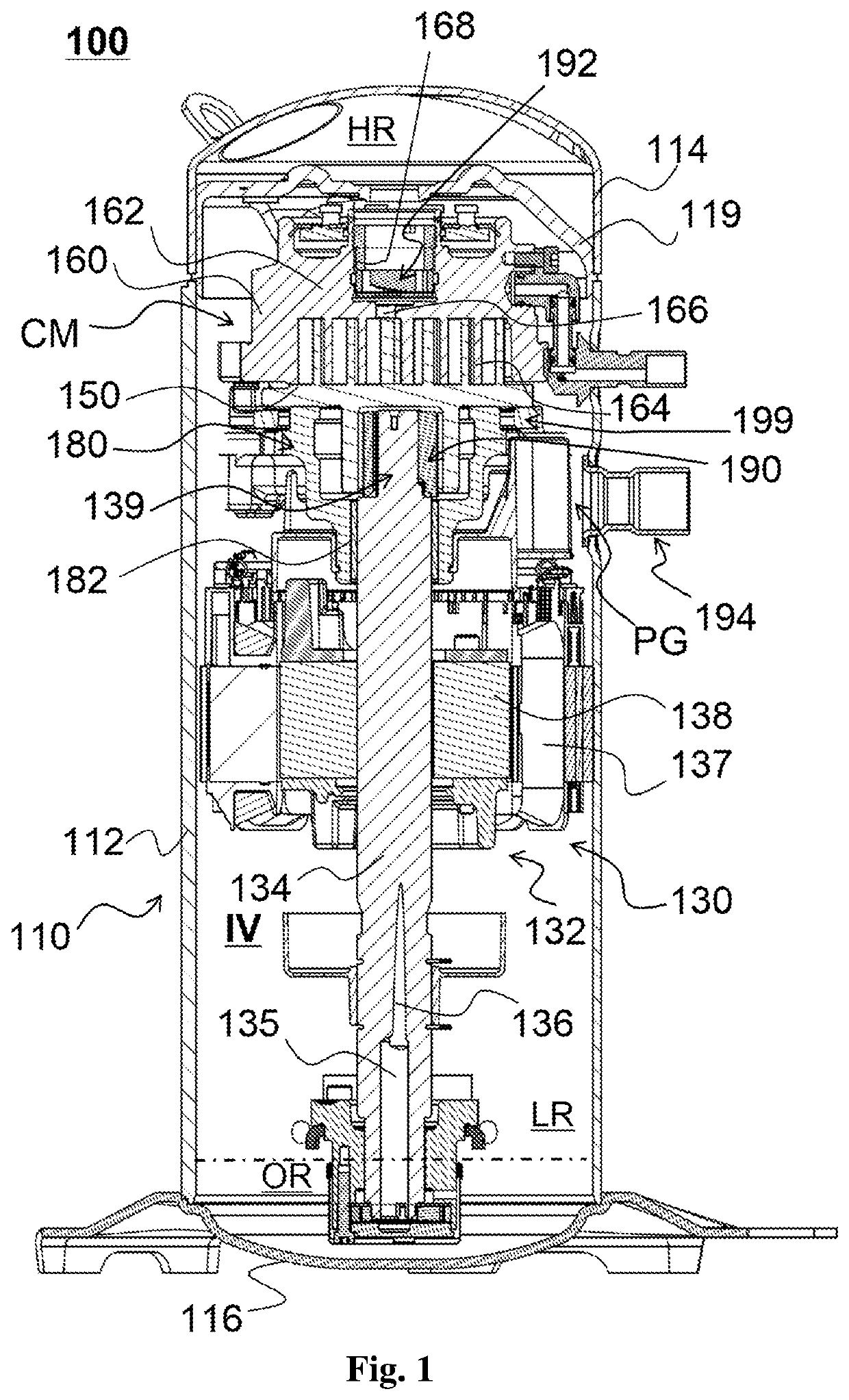
Thus, for example, an excessively high oil circulation rate may cause the lubricant to be accumulated around the discharge valve assembly 192 so as to cause certain issues to the scroll compressor.
Therefore, it is possible to avoid an excessive oil circulation rate which causes the lubricant to accumulate around the discharge valve assembly and brings stability and reliability issues to the scroll compressor.

Method used


Image

  • Lubrication of scroll compressor
  • Lubrication of scroll compressor
  • Lubrication of scroll compressor

Examples


first embodiment

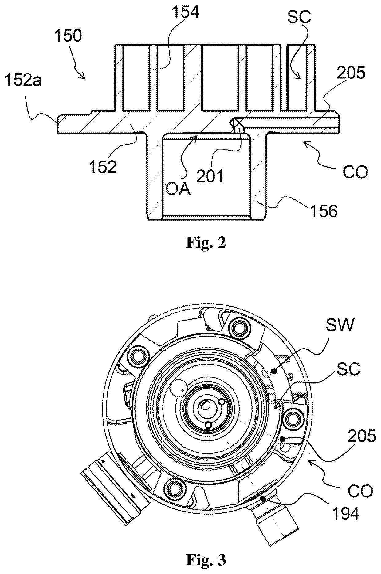
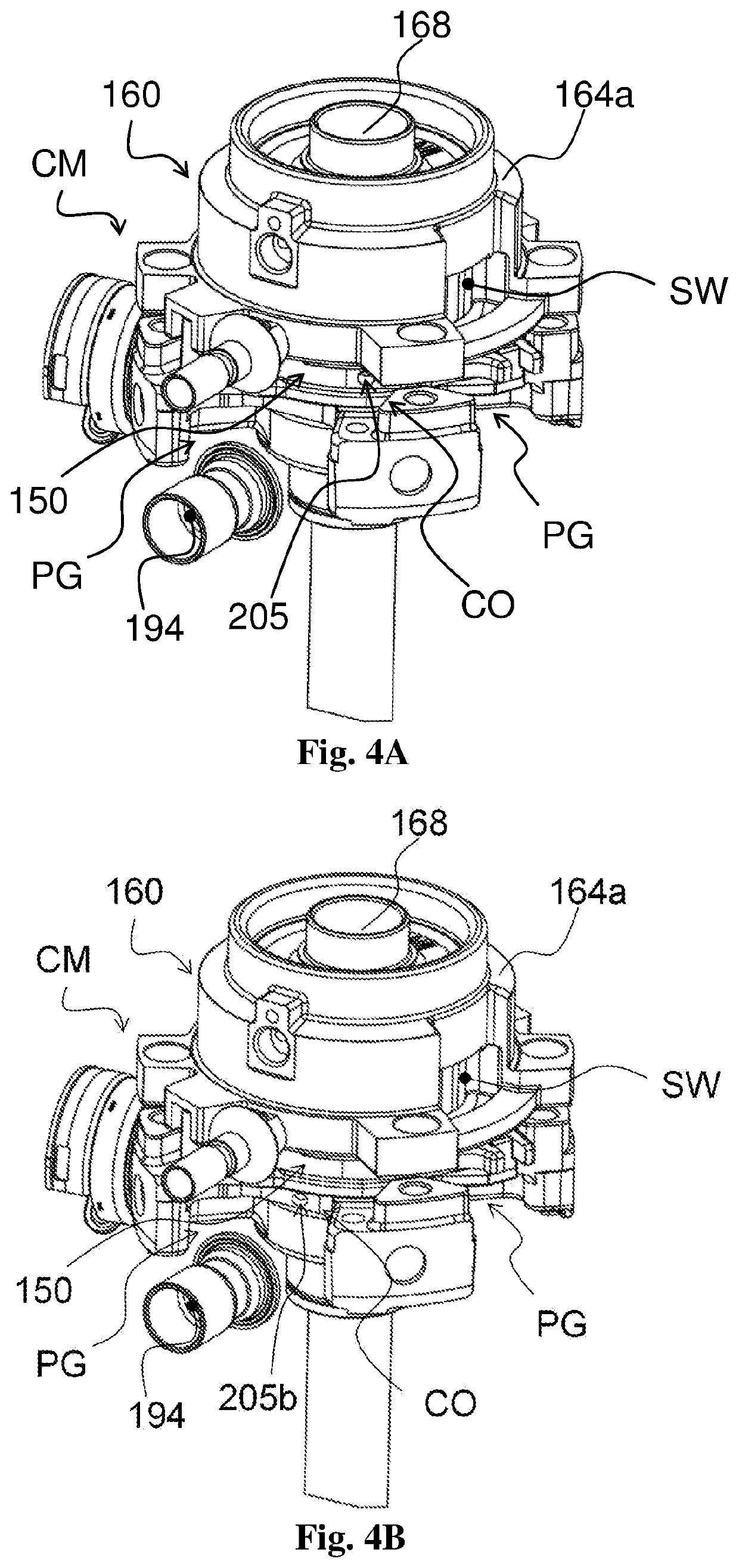
[0051]Reference is particularly made to FIG. 2, and the compression mechanism oil supply device CO according to the present application may include an inlet hole 201 in communication with the lubricant storage area OA and a transverse hole 205 in communication with the inlet hole 201. The inlet hole 201 and the transverse hole 205 may be formed in the orbiting scroll base plate 152. In some examples, the inlet hole 201 is an axial hole extending in the axial direction. However, it is conceivable that the inlet hole 201 may also be an oblique hole inclined with respect to the axial direction. In some examples, the transverse hole 205 is a horizontal hole extending in a radial direction of the compressor. However, it is conceivable that the transverse hole 205 may also be an oblique hole inclined with respect to the radial direction (horizontal direction). Here, it should be noted that the inlet hole 201 and the transverse hole 205 constitute the oil supply passage according to the pr...

second embodiment

[0062]The compression mechanism oil supply device CO of the lubrication system according to the modification of the present application is described below. In this modification, a plug 207 is provided. The plug 207 is adapted to be connected to the counterbore 205a (e.g., by threaded connection). A through hole 207a may be provided in the plug 207, and the through hole 207a may have an appropriate inner diameter. In some examples, the inner diameter of the through-hole 207a may be less than the inner diameter of the remaining section of the transverse hole 205. In other examples, the inner diameter of the through-hole 207a may be equal to or even greater than the inner diameter of the remaining section of the transverse hole 205.

[0063]Accordingly, the compression mechanism oil supply device according to the present application actively causes the lubricant expelled to meet the suctioned low pressure working fluid when the lubricant from the lubricant storage area OA is discharged ou...


PUM


Abstract

A scroll compressor is provided, including: a compression mechanism, a driving mechanism, a suction fitting and a lubrication system. The compression mechanism is adapted to compress working fluid and includes a movable scroll component, a fixed scroll component and a suction window, the working fluid flows into the compression mechanism via the suction window. The driving mechanism includes a driving shaft and is adapted to drive the compression mechanism. The working fluid flows into the scroll compressor via the suction fitting and then flow into the compression mechanism. The lubrication system includes a lubricant source and a compression mechanism oil supply device adapted to supply the lubricant to the compression mechanism from the lubricant source. The compression mechanism oil supply device has an oil supply passage and an outflow opening of the oil supply passage is located between an opening of the suction fitting and the suction window.

Description

[0001]This application is the national phase of International Application No. PCT / CN2016 / 074823, titled “SCROLL COMPRESSOR”, filed on Feb. 9, 2016, which claims the benefit of priorities to Chinese Patent Application No. 201510216987.5 titled “SCROLL COMPRESSOR”, filed with the Chinese State Intellectual Property Office on Apr. 30, 2015, and Chinese Patent Application No. 201520276001.9 titled “SCROLL COMPRESSOR”, filed with the Chinese State Intellectual Property Office on Apr. 30, 2015, the entire disclosures of which are incorporated herein by reference.FIELD OF THE INVENTION[0002]The present application relates to a scroll compressor, and more particularly to a scroll compressor having an improvement in terms of appropriate oil supply for its compression mechanism oil supply device.BACKGROUND OF THE INVENTION[0003]Compressors (such as scroll compressors) can be used in, for example, cooling (freezing or refrigeration) systems, air conditioning systems and heat pump systems. The ...

Claims


Application Information

Patent Timeline
Patent Type & Authority Patents(United States)
IPC IPC(8): F04C29/02F04C18/02F04C23/00F04C29/00
CPCF04C18/0215F04C23/008F04C29/028F04C18/0253F04C29/0057F04C28/08F04C28/22F04C29/023
Inventor MA, WENRUIYU, YINGLINDONG, PEILONGLIANG, SHENGCUI, YONGHUA
Owner EMERSON CLIMATE TECH (SUZHOU) CO LTD
Learn More