Membrane-cleaning method for membrane bioreactor process

a bioreactor and membrane technology, applied in the direction of membranes, separation processes, multi-stage water/sewage treatment, etc., can solve the problems of deterioration of the rate of filtration through the membrane, inability to clean the membrane, and inability to remove sludge, so as to avoid the deterioration of the filtration rate of the separation membrane element through the membrane, the effect of maintaining the level of scraping effect and avoiding the deterioration of the level of scrap

Active Publication Date: 2008-09-09
NGK INSULATORS LTD
View PDF20 Cites 18 Cited by
  • Summary
  • Abstract
  • Description
  • Claims
  • Application Information

AI Technical Summary

Benefits of technology

[0008]According to the invention of claim 1, membrane-cleaning particles in which a surface that makes contact with water to be treated is hydrophilized, and asperities of a surface that makes contact with a separation membrane element are not less than 100 μm and not more than 2500 μm are caused to flow, and deposits choke up a surface of the separation membrane element is scrapped off. In addition, if bubbles are generated in the interior, since a surface that makes contact with water to be treated is hydrophilized, bubbles are rapidly removed. Further, since asperities of a surface that makes contact with the separation membrane element are made to be not less than 100 μm and not more than 2500 μm, deposits adherent to a surface of the separation membrane element can be effectively scraped off. As a result, deterioration in the rate of filtration of the separation membrane element through the membrane can be avoided. Further, when the particles are of a spongy network structure, the surface that makes contact with water to be treated, means in this context refers to a surface of a particle material.
[0009]According to the invention of claim 2, since a particle is made of a non-pore or a closed-pore material, the membrane-cleaning particle has no pore that communicates with the interior. Therefore, since bubbles are not generated in the interior, and do not float on an upper part of a biological reaction tank, the level of cleaning effects can be maintained. According to the invention of claim 3 or 4, since a membrane-cleaning particle is used that carries an antibacterial component such as silver and copper, it becomes difficult for microbes to become attached to a surface of the membrane-cleaning particle. For this reason, any deterioration in the level of scraping off effects caused by formation of a soft microbe membrane on the surface of the membrane-cleaning particle can be prevented. Further, according to the invention of claim 5, since a membrane-cleaning particle is brought into an anaerobic condition, and microbes on a particle surface are peeled off, any deterioration in the level of scraping off effects can be prevented. As a result, any deterioration in the rate of filtration of the separation membrane element through the membrane can be avoided.

Problems solved by technology

However, since for such a method a large scale settling tank is required, in for example, sewage treatment plants in cities where sizes of site are necessarily limited, a membrane bioreactor process is being studied of arranging a separation membrane element in the interior of a reaction tank, of performing solid-liquid separation, and of taking out treated liquid as membrane-filtered water.
This method makes a large-scale settling tank unnecessary.
However, in the membrane bioreactor process, a danger arises that sludge will deposits adherent to a surface of a separation membrane, and that within a short space of time the rate of a filtration through the membrane will deteriorate.
However, in a conventional spongy floating solid, bubbles are gradually generated in communicating pores in the interior thereof, and, because, due to the hydrophobicity of the material used for the floating solid, it is difficult to remove the bubbles from spongy floating solid, spongy floating solid float on the upper part of a biological reaction tank, the effects of membrane-cleaning are easily lost.
In addition, it is easy for the surface of the spongy floating solid to become gradually covered with microbes, or with ex vivo substances thereof, and since these are too soft, the effects of scraping off deposits (a scale layer) adherent to a membrane surface can not be obtained.
Further, when a membrane-cleaning particle having few asperities is used on a surface of the floating solid, a problem has arisen that the scraping off of deposits (scale layer) adherent to a membrane surface has not been performed effectively.

Method used


Image

  • Membrane-cleaning method for membrane bioreactor process
  • Membrane-cleaning method for membrane bioreactor process

Examples


example 1

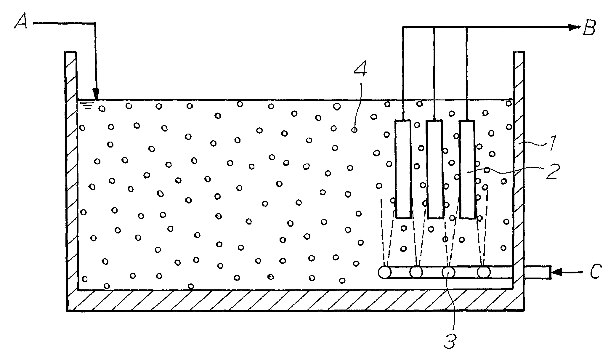
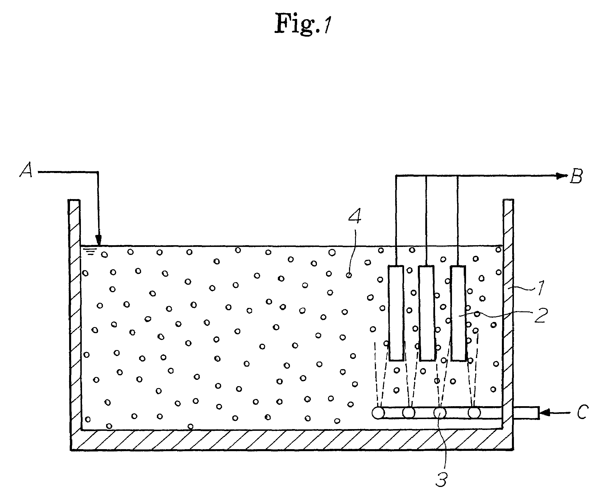
[0027]In order to investigate the effects of the membrane-cleaning particle, a comparative experiment was performed with the use of two kinds of cubic particles (a hydrophilic polyurethane sponge and a hydrophobic polyurethane sponge). Hydrophilization of the hydrophilic polyurethane sponge was performed by means of treatment such that a surface that makes contact with water to be treated is covered with polyethylene glycol (hydrophilic). Asperities of a particle surface are 1.0 mm in both cases. As the biological reaction tank, an apparatus of a Ludzack process type consisting of a denitrogenated basin and a nitrification tank was used. As the separation membrane element, six polymer flat membranes having an effective area of 0.4 m2 per membrane were submersed into a nitrification tank so as to obtain treated water. Leachate served as treatment wastewater. The membrane-cleaning particle was placed into the nitrification tank at a volumetric ratio of 0.7%. In addition, an operation ...

example 2

[0029]In order to investigate the effects of the membrane-cleaning particle, a comparative experiment was performed with the use of five kinds of spherical particles (hydrophilic polyurethane sponge) that had varying level of asperities. Asperities of a particle surface were 50 μm, 100 μm, 1000 μm, 2500 μm, or 3000 μm. As the biological reaction tank, a Ludzack process-type apparatus consisting of a denitrogenated tank and a nitrification tank was used. As the separation membrane element, six polymer flat membranes having an effective area of 0.4 m2 per membrane were submersed into a nitrification tank so as to obtain treated water. Sewage served as the treatment wastewater. The membrane-cleaning particle was introduced into the nitrification tank at a volumetric ratio of 0.7%. In addition, the operation was performed at an MLSS (mixed liquor suspended solids) of 5000 mg / L in the biological treatment tank. A membrane filtration flux was initiated at 0.8 m / day at the start of experim...


PUM

PropertyMeasurementUnit
specific gravityaaaaaaaaaa
pore diameteraaaaaaaaaa

Abstract

A method of cleaning a membrane in a membrane separation activated-sludge process. By the method, deposits adherent to the surface of a membrane used in a membrane separation activated-sludge process can be effectively scratched off and the membrane filtration rate can be prevented from decreasing. Membrane-cleaning particles (4) in which the surface to be in contact with the water to be treated has been hydrophilized and has a surface roughness of 100-2,500 μm are introduced into a bioreactor (1). The particles are caused to flow by the lifting effect of air bubbles ejected from an aerator (3) or by the fluidizing effect of a fluidizing means to thereby cause the particles to scratch off deposits adherent to the surface of a separation membrane element (2). In one embodiment, membrane-cleaning particles (4) which are non-porous or have closed cells are used. In another embodiment, membrane-cleaning particles (4) having an antibacterial ingredient, such as copper or silver, supported on the surface or in inner parts thereof are used. In a still another embodiment, the membrane-cleaning particles (4) are periodically brought into an anaerobic condition to remove microorganisms from the particle surface.

Description

TECHNICAL FIELD[0001]The present invention relates to a membrane-cleaning method for a membrane bioreactor process used in wastewater treatment in sewage treatment plants.BACKGROUND OF THE INVENTION[0002]When organic wastewater is treated by activated sludge-process, a method of providing a settling tank behind a biological reaction tank, and of settlement-separating sludge and filtrate, is normal. However, since for such a method a large scale settling tank is required, in for example, sewage treatment plants in cities where sizes of site are necessarily limited, a membrane bioreactor process is being studied of arranging a separation membrane element in the interior of a reaction tank, of performing solid-liquid separation, and of taking out treated liquid as membrane-filtered water. This method makes a large-scale settling tank unnecessary.[0003]However, in the membrane bioreactor process, a danger arises that sludge will deposits adherent to a surface of a separation membrane, a...

Claims


Application Information

Patent Timeline
Patent Type & Authority Patents(United States)
IPC IPC(8): C02F3/00
CPCB01D65/02B01D65/08C02F3/1273B01D2315/06C02F2303/16B01D2321/2091C02F1/505B01D2321/185Y02W10/10B01D65/04
Inventor NOGUCHI, MOTOHARU
Owner NGK INSULATORS LTD
Why Eureka
Try Eureka