Device for thawing frozen pipes

a technology for thawing pipes and pipes, applied in water mains, water installations, construction, etc., can solve the problems of requiring more space to store or store, affecting the functionality of pipes, and bursting pipes or cracks, etc., to achieve the effect of convenient, simple and low cost methods

Active Publication Date: 2020-05-12
REILLY JR PATRICK ANTHONY +1
View PDF19 Cites 0 Cited by
  • Summary
  • Abstract
  • Description
  • Claims
  • Application Information

AI Technical Summary

Benefits of technology

[0003]The present invention provides a reliable and affordable device to thaw frozen pipes without the need to determine the location of the frozen section of the pipe.
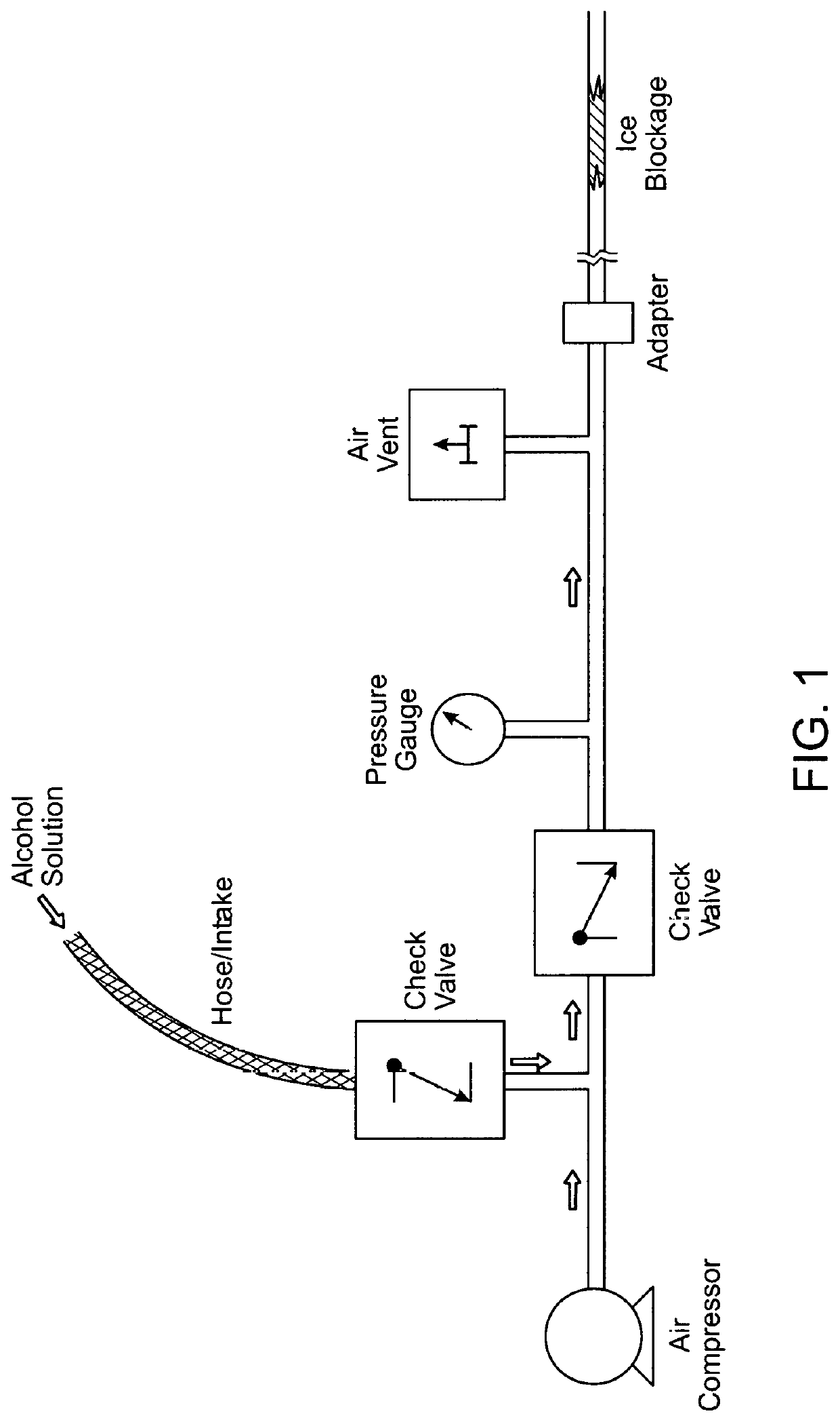
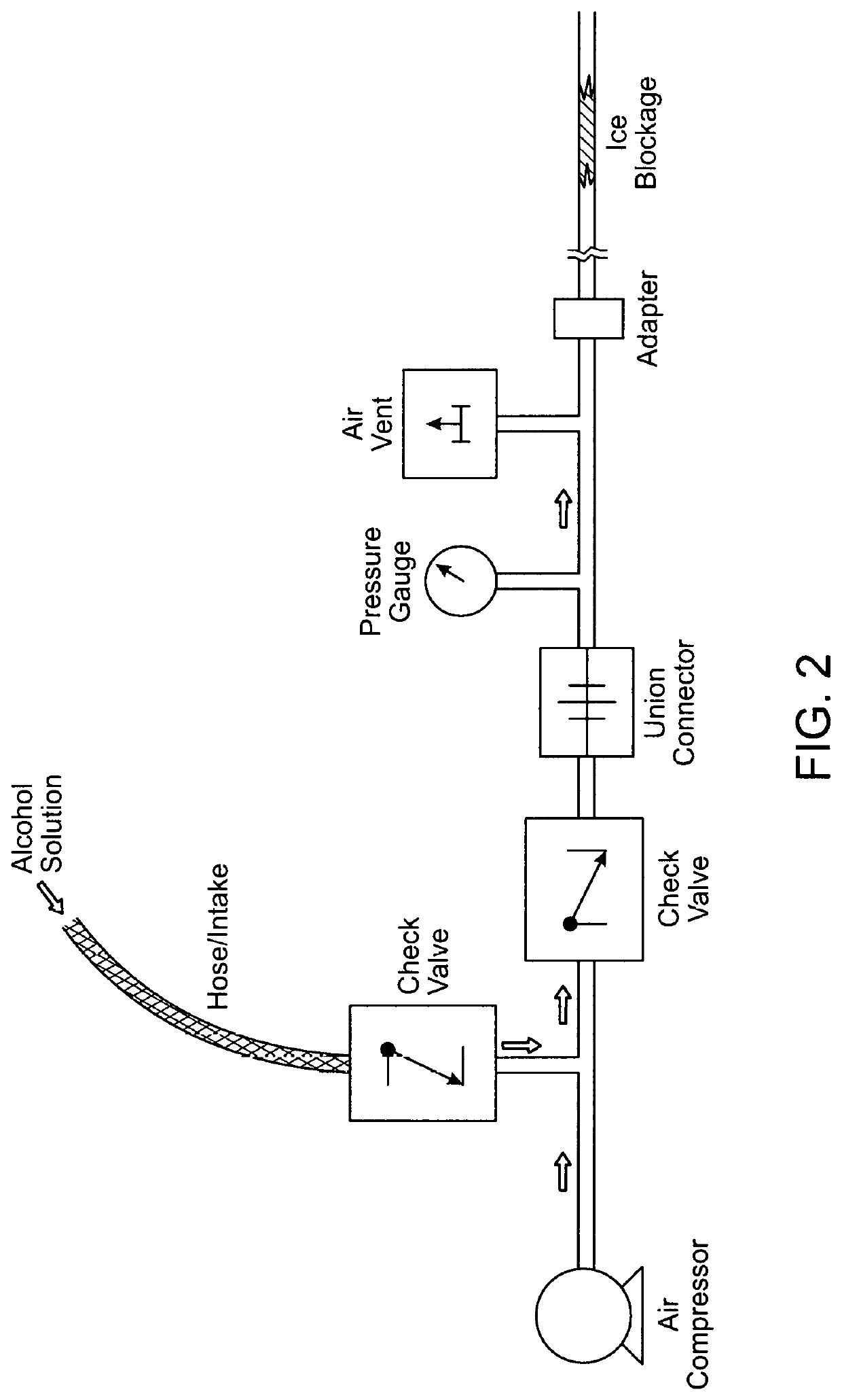
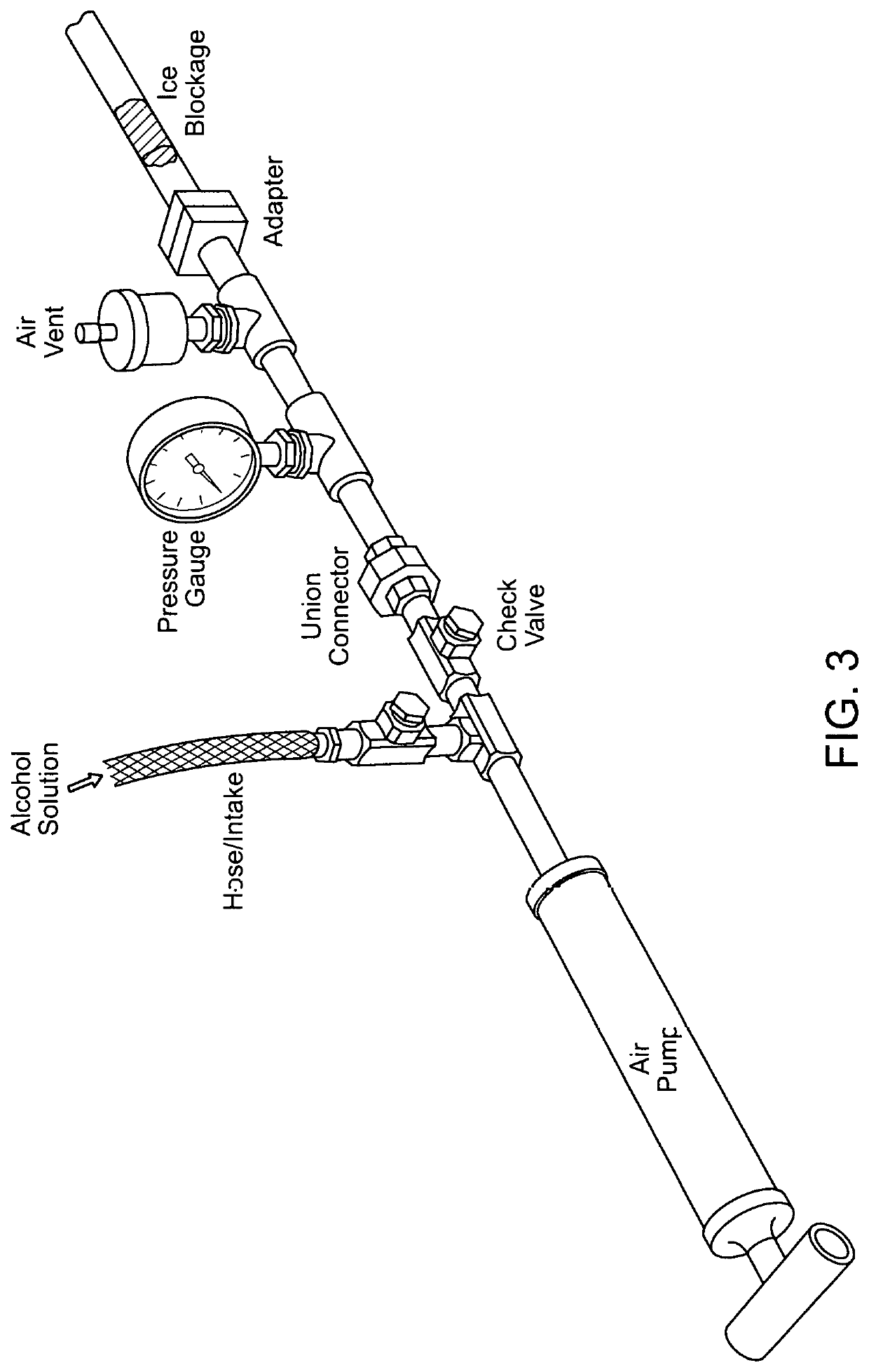
[0013]In between each check valve, gauge, vent and the pump are short lengths of pipe or tubing to aide in connecting the various components. The pipe or tubing of the apparatus may be made of standard ferrous-based plumbing materials such as brass, copper or black pipe or any other suitably strong and rigid materials.
[0017]It is a feature of the invention that the device can utilize ½ inch pipe fittings, ¾% inch pipe fittings or larger diameter fittings. Higher diameter pipe fittings would allow for larger application including higher capacity industrial uses.
[0019]The device can be configured to attach to the affected pipe in a straight line or at an angle depending on the adapter or connector used. This assists in the use of the device in locations where space is restricted. For example, the device will function in the same way even with a ninety-degree adapter fitted to the device and connecting it to the blocked pipe.
[0023]The handheld embodiment of the device works by first connecting the device to the effected pipe using the appropriate adapter at the end opposite from the air pump. The unattached end of the flexible intake hose or tube is placed in a bucket of alcohol solution. The operator then begins pumping the pump handle. Positive air pressure is created within the device which draws an alcohol solution from a separate container connected into the apparatus via the intake hose. The alcohol solution is injected into the device through the intake hose or tube connected to the apparatus via a check valve. The check valve connected to the intake hose prevents the pressurized air from inside the device from escaping into the intake hose while allowing the alcohol solution to be drawn through it into the device. The check valve further functions to allow only one-way flow of air or liquids, preventing back-flow and maintaining positive air pressure within the device. The alcohol solution is pushed through the device and through a second check valve further along the apparatus. The check valve is connected to a length of pipe or tubing which is then connected to a pressure gauge. The pressure gauge provides the operator with the ability to monitor the pressure in the pipe and avoid over-pressurizing the pipe and causing damage to it. The pressure gauge is connected to a length of pipe or tubing which is connected to an adjustable air vent. The adjustable air vent, which allows only one-way, outgoing airflow relieves excess air pressure while preventing air from entering the device.
[0025]When the alcohol solution reaches the ice blockage, the pressure building up behind it will force the solution to flow around the ice, melting the outer layers of ice until the ice is loosened and eventually detaches from the walls of the pipe, relieving the blockage.

Problems solved by technology

Other pipe thawing devices or methods may achieve the same end result, however they typically require access to the frozen section of the pipe, knowledge of where the frozen section is, or employs hot water which can result in burst or cracked pipes from sudden temperature changes.
Further, other pipe thawing devices are more complicated or difficult to use, are more costly to produce, require more space to store or are limited in their functionality.

Method used


Image

  • Device for thawing frozen pipes
  • Device for thawing frozen pipes
  • Device for thawing frozen pipes

Examples


Embodiment Construction

[0041]The detailed description provided below in connection with the drawings is intended as a description of the present examples and is not intended to represent the only forms in which the present example may be constructed or utilized. The description sets forth the functions of the example and the sequence of steps for constructing and operating the example. However, the same or equivalent functions and sequences may be accomplished by different examples.

[0042]For convenience, certain terms employed in the entire application (including the specification, examples, and appended claims) are collected here. Unless otherwise defined herein, scientific and technical terminologies employed in the present disclosure shall have the meanings that are commonly understood and used by one of ordinary skill in the related art. Unless otherwise required by context, it will be understood that singular terms shall include plural forms of the same and plural terms shall include the singular. Sp...


PUM


Abstract

Disclosed herein is a device for injecting pressurized alcohol solution into a pipe located in a house or other structure that carries water. The device allows the user to control and adjust the pressure of the injected alcohol solution. The pressure forces the alcohol solution against the frozen water inside the pipe. The alcohol solution then acts to dissolve the ice, thereby clearing the blockage and preventing damage to the pipe. The device is hand held, portable and configurable. The embodiment of the device with the hand-operated pump does not require electricity or other sources of power. Alternate embodiments of the device can be broken down into two or more sections for easier storage. Alternate embodiments of the device has one or more of the lengths of connecting pipe or connector or adapter bends at an angle so that the device is not configured in a straight line but has a bend or curve. These alternate embodiments allows for the device to fit into tight or restricted spaces. Alternate embodiments of the device utilize fittings, connectors, valves, gauges, vents and lengths of pipe of different sizes, lengths, diameters and materials. Different solutions or solvents other than an alcohol solution may be used. Also disclosed is the method of using the device.

Description

BACKGROUND OF THE INVENTION1. FIELD OF THE INVENTION[0001]The present disclosure relates generally to the field of plumbing devices, more particularly the thawing of frozen water pipes within a building. The mechanical device utilizes air pressure to inject an alcohol solution into pipes to remove blockages caused by water frozen within the pipe.2. SUMMARY[0002]The following presents a simplified summary of the disclosure in order to provide a basic understanding to the reader. This summary is not an extensive overview of the disclosure and it does not identify key / critical elements of the present invention or delineate the scope of the present invention. Its sole purpose is to present some concepts disclosed herein in a simplified form as a prelude to the more detailed description that is presented later.[0003]The present invention provides a reliable and affordable device to thaw frozen pipes without the need to determine the location of the frozen section of the pipe.[0004]In par...

Claims


Application Information

Patent Timeline
Patent Type & Authority Patents(United States)
IPC IPC(8): F16L53/00E03B7/14
CPCE03B7/14
Inventor REILLY, JR., PATRICK ANTHONYDECAREAU, JAMES FRANCIS
Owner REILLY JR PATRICK ANTHONY
Why Eureka
Try Eureka