Illuminated display device

a technology of illumination display and display case, which is applied in the direction of lighting support device, instruments, signs, etc., can solve the problems of limited display space and proper display implementation, poor practical effect, and inability to achieve desirable characteristics of prior art displays and signs, etc., to achieve convenient and safe use, small thickness, and good practicability

Inactive Publication Date: 2006-06-27
WOODRUFF MICHAEL A
View PDF25 Cites 27 Cited by
  • Summary
  • Abstract
  • Description
  • Claims
  • Application Information

AI Technical Summary

Benefits of technology

[0016]The present invention not only imparts the characteristics lacking in the prior art but also contains many other attributes required for an ideal display device. To successfully deliver the message, the device is effective, efficient, durable, practical, easy and safe to use, as well as reliable and affordable. The preferred embodiment of the invention has a very small thickness because it is made using an LED, a button-like battery, and a thin switch. These are attached to a very thin static cling film, providing a display device that does not protrude into a room, nor does it rest upon a window sill or hang from a window frame. This causes the invention to be extremely safe inasmuch as it is virtually impossible to unintentionally remove from the substrate, such as a window.
[0017]The invention is lightweight, simple in design with minimal components, and is easily and quickly attached to and removed from the substrate without damaging the surface to which it is attached. In addition, the design allows for quick and easy changes of the displayed indicium or indicia. The invention represents significant improvements and advantages over, and exceeds the capabilities of, all prior related inventions of record.

Problems solved by technology

The preparation of a new glass sheet, coupled with shipping precautions due to the frailty of glass, makes such signs very expensive.
Furthermore, as these signs increase in size, the practical problems of limited display space and proper display implementation become controlling due to weight and size considerations.
However, such prior art displays and signs are still lacking in desirable characteristics.
Because these lamps are unstable, they are often secured by wire or other fasteners to prevent people or pets from knocking the lamps off the sills, where they can be destroyed or the glass bulb can be shattered, thereby causing a safety hazard.

Method used


Image

  • Illuminated display device
  • Illuminated display device
  • Illuminated display device

Examples


Embodiment Construction

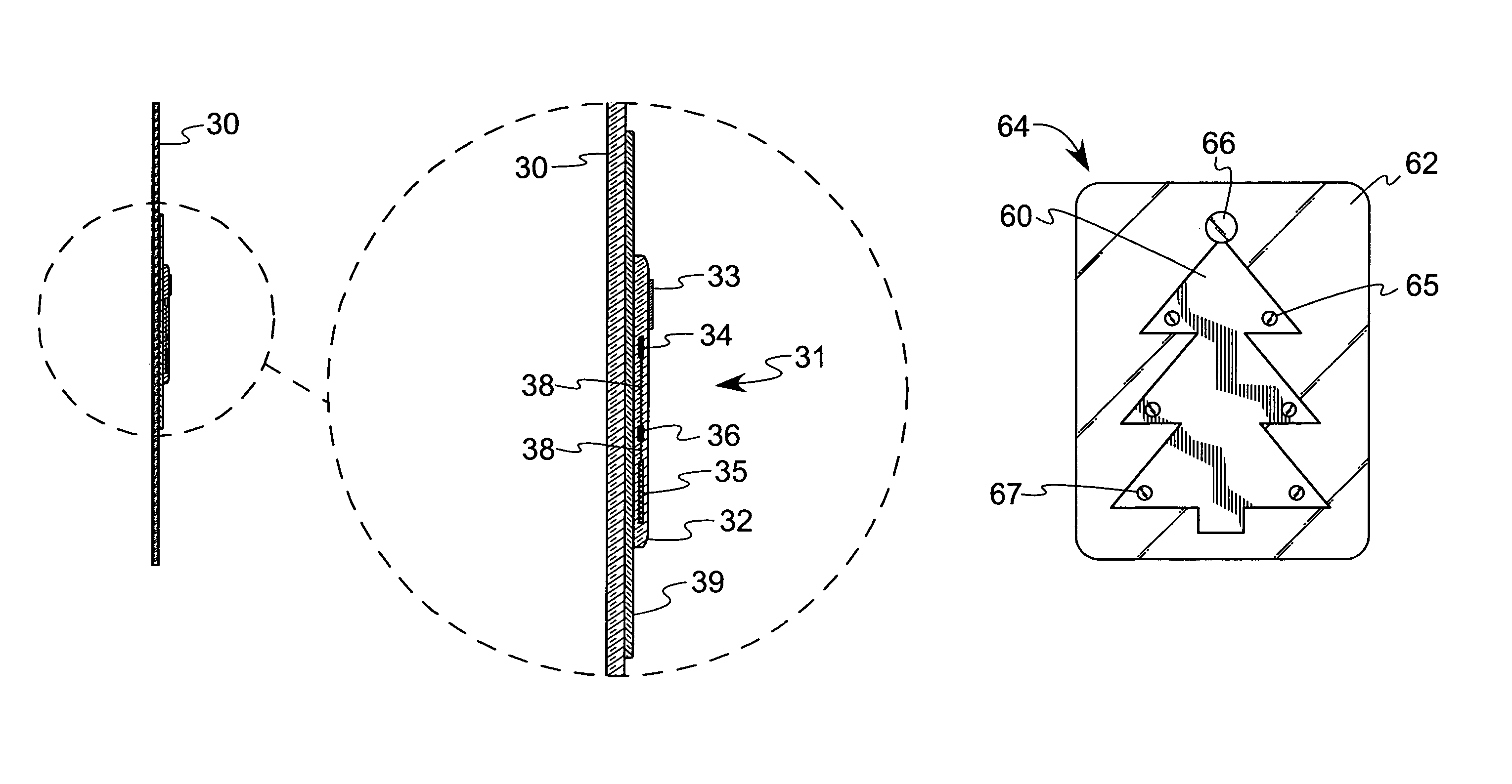
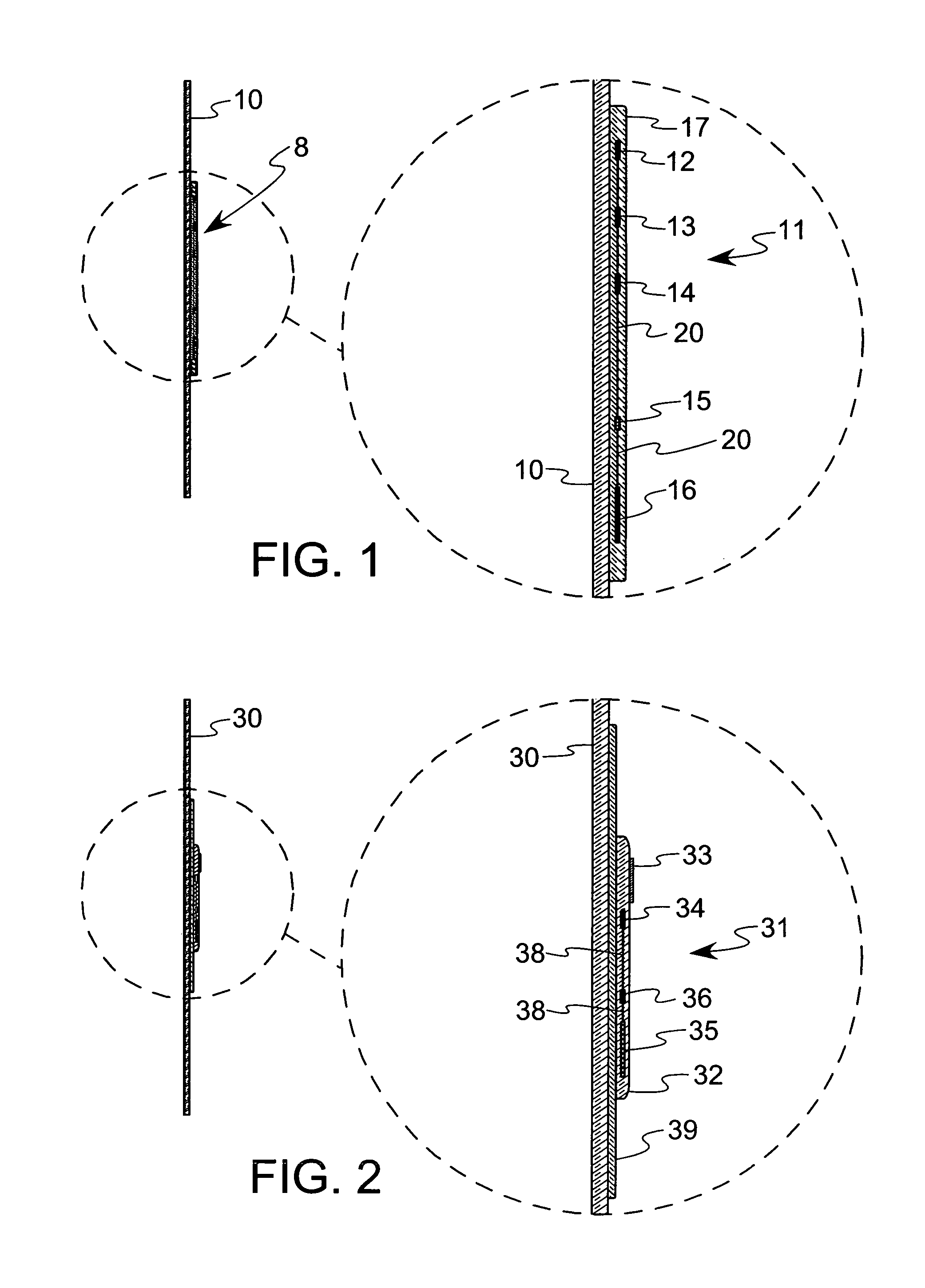
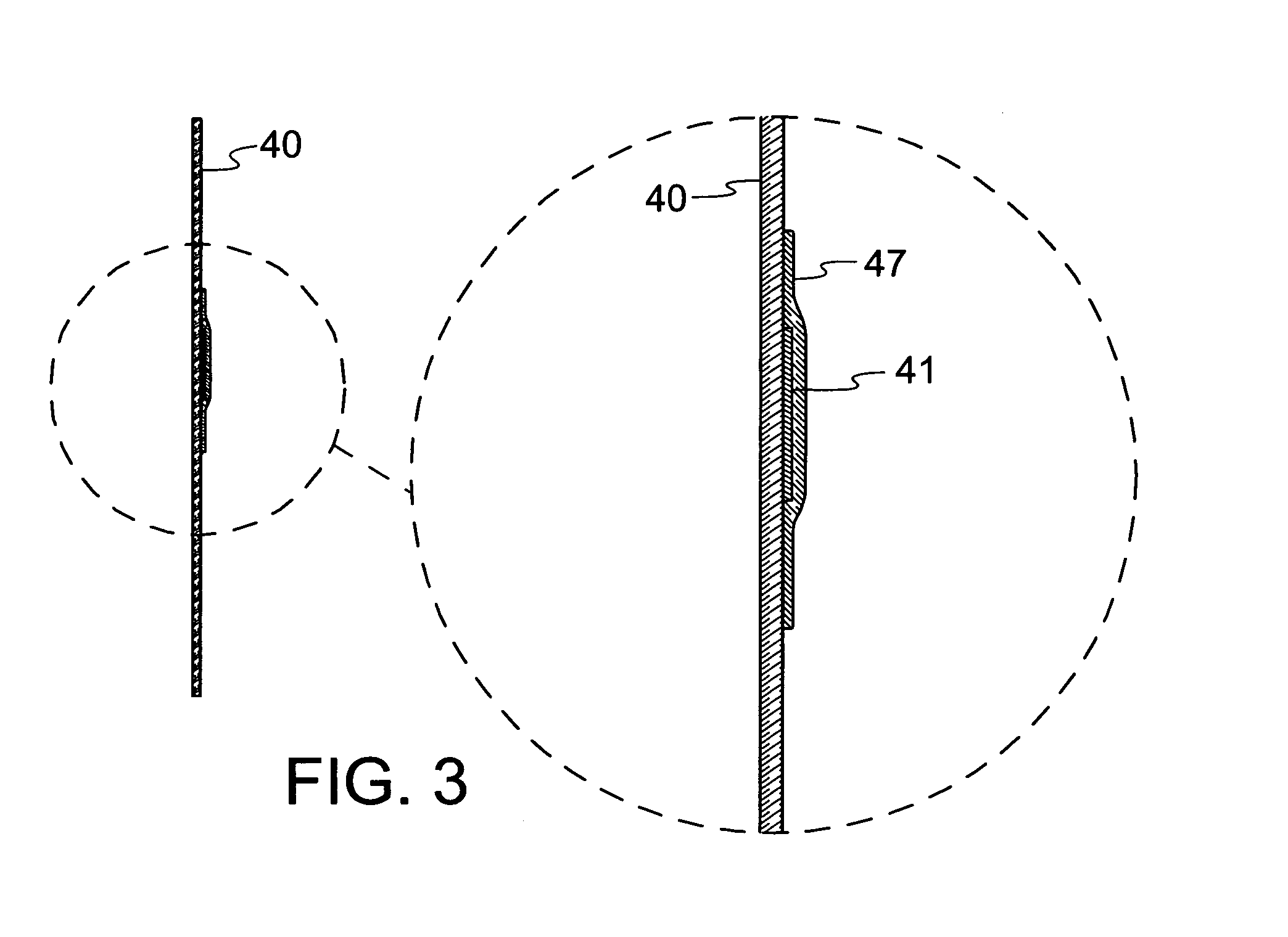
[0025]The preferred embodiment of the present invention is shown in FIG. 1, in which a display device 8 is mounted to a substrate, such as the surface of the glass window 10, which is oriented vertically. The window 10 can be, for example, a window in a home, place of business or automobile. Virtually any surface can function as the substrate to which the present invention is attached, and the substrate need not be vertically oriented, although this is preferred in order to reduce any non-shear forces that tend to remove the display device. The substrates include, but are not limited to, walls, mirrors, windows, doors, appliances, skylights and sunroofs.

[0026]The display device 8 includes a static cling mounting film, such as the polymer film 17, that is mounted to the substrate by static attraction between the film 17 and the glass window 10. In the FIG. 1 embodiment there is no adhesive interposed between the film 17 and the window 10. Attached to the mounting film is an illuminat...


PUM


Abstract

A display device that can be mounted to a surface, such as a window, using static attraction. The display device has an illumination assembly circuit including a light source (such as an LED), a power supply (such as a battery) and a switch interposed therebetween. The illumination assembly is either attached to or enclosed within a mounting film, such as a flexible polymer that is electrostatically attracted to a surface. A preferred device has indicia printed on it to display, and with which the LEDs cooperate.

Description

BACKGROUND OF THE INVENTION[0001]1. Field of the Invention[0002]This invention relates generally to a display device for decoration, advertising or education, among others, and, more specifically, to an illuminating display device with a light source and a mounting assembly for mounting the display device to a surface.[0003]2. Description of the Related Art[0004]Displays are used in a wide variety of applications such as promotions, advertising, decorations, and as signs to communicate information or warnings. Many retail stores employ display signs for decoration or to indicate whether the store is open or closed.[0005]Common display signs carry a message or design imprinted thereon. A display sheet can be mounted within a frame having a light source therein. The front face of the sheet may be lighted by lights located along the periphery of the frame. Alternatively, when using a transparent or translucent sheet, back lighting may also be employed.[0006]The prior art includes displ...

Claims


Application Information

Patent Timeline
Patent Type & Authority Patents(United States)
IPC IPC(8): G09F13/22G09G
CPCG09F7/12
Inventor WOODRUFF, MICHAEL A.
Owner WOODRUFF MICHAEL A
Why Eureka
Try Eureka