
Protection against excessive forces in a suspension arrangement

a suspension arrangement and protection technology, applied in the direction of vibration suppression adjustment, mechanical equipment, transportation and packaging, etc., can solve the problems of preventing normal use, affecting the safety of passengers, and the isolation properties of soft isolation alone cannot be used, so as to improve the isolation properties of suspension, reduce the impact transmitted, and increase the durability

Active Publication Date: 2017-06-08
TEKNOLOGIAN TUTKIMUSKESKUS VTT
View PDF2 Cites 1 Cited by
  • Summary
  • Abstract
  • Description
  • Claims
  • Application Information

AI Technical Summary

Benefits of technology

The proposed suspension arrangement provides better isolation properties, meaning it can protect against sudden shocks and impacts, compared to conventional methods. It is reversible, meaning it can be used multiple times, and it reacts quickly to shocks and vibrations. Additionally, it is simpler and more reliable than other systems, meaning it can withstand more use and is more affordable.

Problems solved by technology

However, in most applications soft isolation alone cannot be used because maximised isolation will typically make the object unstable thus preventing the normal use thereof.
Such a passive suspension is therefore not ideal.
Whether the adjustment is made by the user or automatically by a sensor arrangement, such systems have a tendency to be quite complicated and therefore expensive and delicate.

Method used


Image

  • Protection against excessive forces in a suspension arrangement
  • Protection against excessive forces in a suspension arrangement
  • Protection against excessive forces in a suspension arrangement

Examples


Embodiment Construction

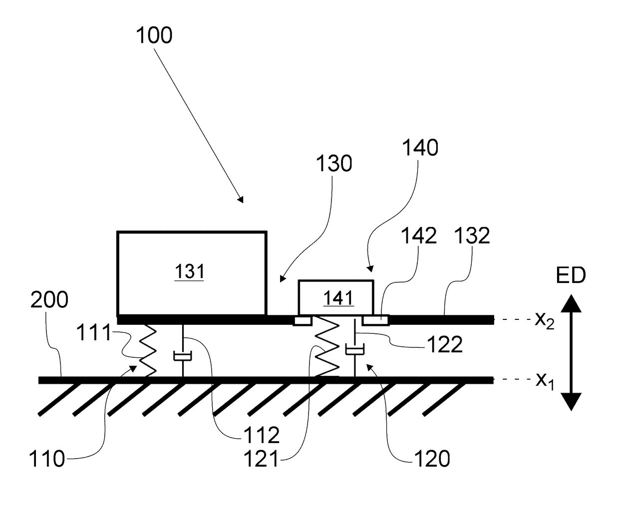
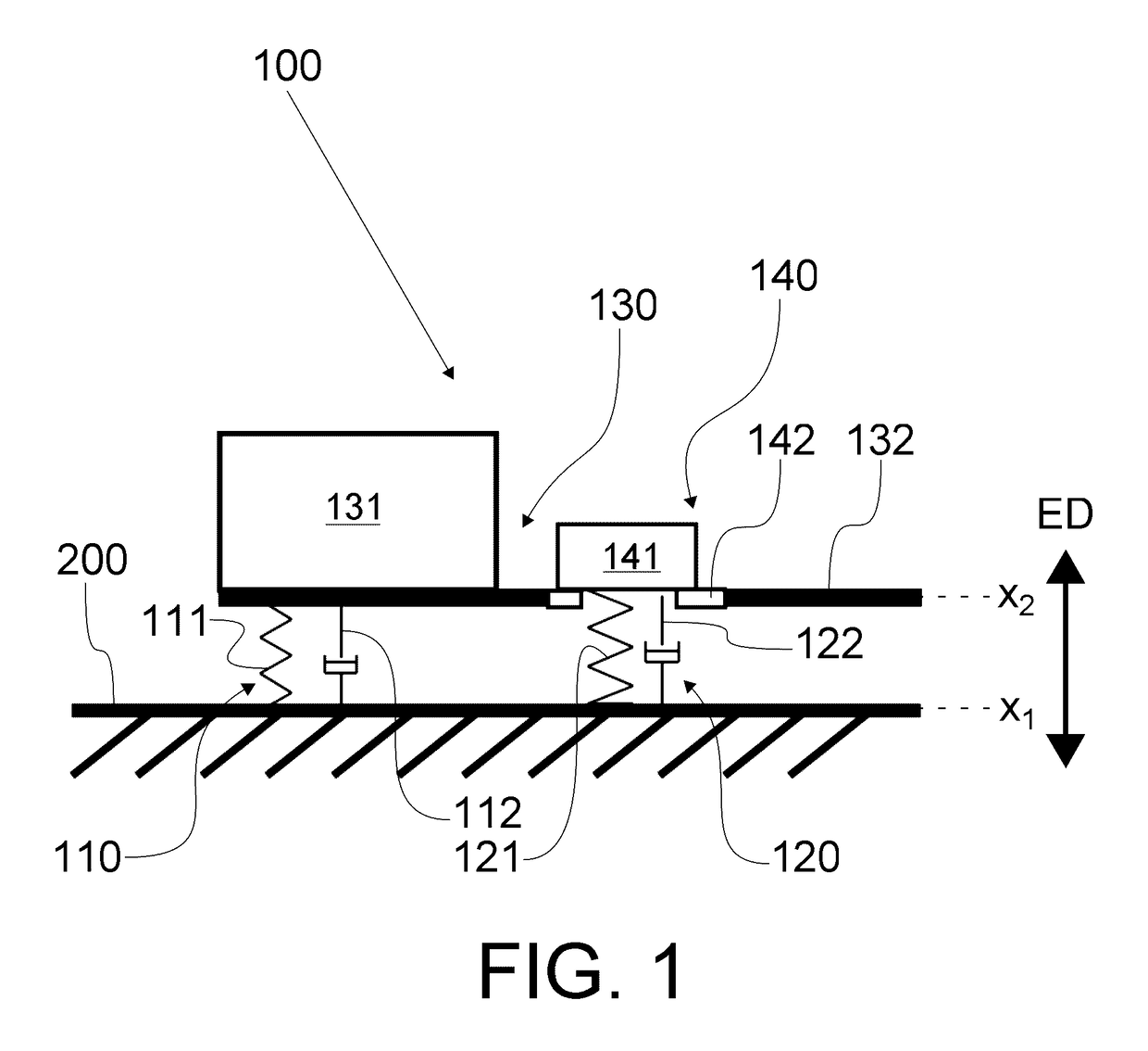
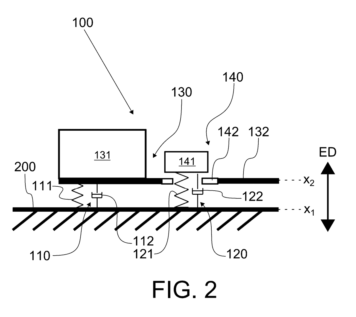
[0025]An exemplary embodiment is described with reference to FIGS. 1 and 2, wherein a simple suspension arrangement 100 is illustrated. In the shown example, an object 130 is suspended to a frame 200 by means of two suspension elements, namely a first and second suspension element 110, 120, respectively. The first and second suspension elements 110, 120 are coupled to the object 130 via a coupling interface 132, which in the FIGS. has been depicted as a mere platform connecting the suspension elements 110, 120 to the object 130 in parallel. It would also be possible to arrange the suspension elements 110, 120 on opposite sides of the object 130, whereby the frame 200 would surround the object 130 (not shown). The coupling interface 132 connects to or forms part of a mass 131, which is to be suspended to the frame 200. In the illustrated example, the mass 131 is approximated to form all of the mass of the object 130, whereas the coupling interface 132 is assumed weightless. Instead o...


PUM


Abstract

A simple and robust suspension arrangement is provided for taking into account different suspension modes without the need for excessive sensoring or electronics. The novel suspension arrangement includes a first suspension element, which directly suspends the object to the frame, and a second suspension element, which suspends the object to the frame through a magnetic coupling between the object and the second suspension element. The magnetic coupling provides a magnetic coupling force (Fh) to act as a threshold such that the suspension arrangement is designed to magnetically decouple the second suspen-sion element from the object when the excitation force (Fe) transmitted be-tween the frame and the object exceeds the magnetic coupling force (Fh).

Description

FIELD OF THE INVENTION[0001]The present invention relates to suspension arrangements. More specifically, the invention relates to a suspension arrangement according to the preamble portion of claim 1.BACKGROUND ART[0002]Suspending an object to a frame is a compromise between stability and comfort. In order to protect equipment, personnel or a structure, such as a vehicle against shocks, the suspension should be soft enough to absorb impacts between the frame and the suspended object. However, in most applications soft isolation alone cannot be used because maximised isolation will typically make the object unstable thus preventing the normal use thereof. On the other hand, the suspension between the object and frame should be rigid during normal operation in order to keep the stability and also prevent the isolated or suspended personnel from feeling sickness from the low frequency oscillation. Let us consider the suspension of a vehicle for example. During driving on a smooth surfa...

Claims


Application Information

Patent Timeline
Patent Type & Authority Applications(United States)
IPC IPC(8): F16F15/03F16F15/18
CPCF16F15/03F16F2230/24F16F15/18B60G17/0152B60G17/019B60G2401/17F16F15/02B60G13/003F16F15/00B60G2204/128B60G17/00
Inventor KEINANEN, JARKKOVEHVILAINEN, KALLEVESSONEN, ISMO
Owner TEKNOLOGIAN TUTKIMUSKESKUS VTT
Learn More