Stamping device and stamping insert, especially as a replacement part for a stamping device

a stamping device and stamping insert technology, which is applied in the field of stamping inserts and stamping devices, can solve the problems of no space, and achieve the effects of improving the stability of stamping parts, simple design, and increasing print quality

Active Publication Date: 2020-05-19
TRODAT GMBH
View PDF126 Cites 2 Cited by
  • Summary
  • Abstract
  • Description
  • Claims
  • Application Information

AI Technical Summary

Benefits of technology

[0007]An object of the present invention is to provide a stamp, an ink pad, a closure cap and a transport system for a stamp band and a method in which improved stability of the stamp parts for increasing the print quality is provided. At the same time a simple design is to be achieved. Another object is to allow customization of the stamp as late as possible.

Problems solved by technology

The disadvantage of a self-inking stamp with central strut is that there is no space for integrating a viewing window, and thus the replica of the stamp image is arranged with an offset and extends to the lateral surface of the bottom part.

Method used


Image

  • Stamping device and stamping insert, especially as a replacement part for a stamping device
  • Stamping device and stamping insert, especially as a replacement part for a stamping device
  • Stamping device and stamping insert, especially as a replacement part for a stamping device

Examples


embodiments

[0093]It should be stated by way of introduction that, in the individual embodiments, the same parts are provided with the same reference numbers or same component designations, wherein the disclosures contained in the entire description can, by analogy, be transferred to same parts with same reference numbers or same component designations. The position details selected in the description, such as, e.g., top, bottom, lateral, etc., relate to the figure described, and in the event of a change of position, they are to be transferred to the new position by analogy. Individual features or feature combinations from the exemplary embodiments shown and described may also represent independent inventive solutions.

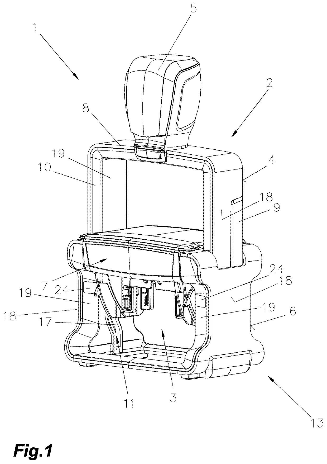
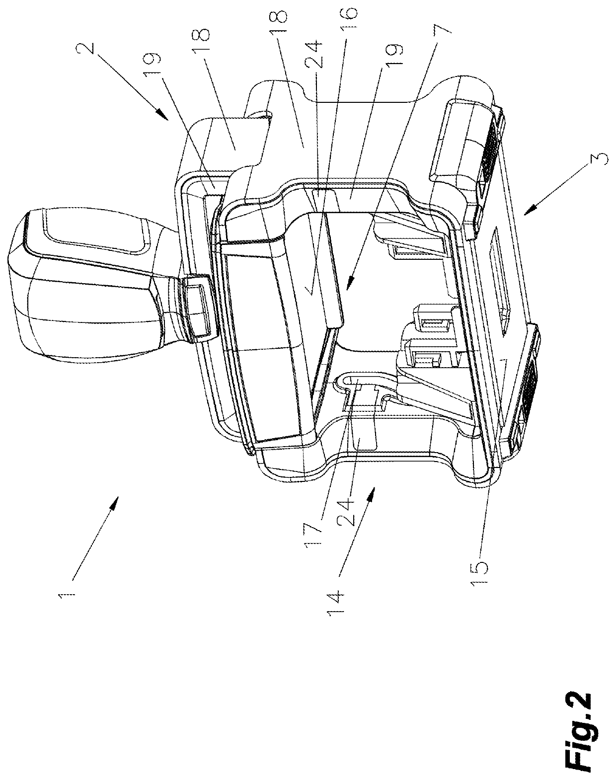
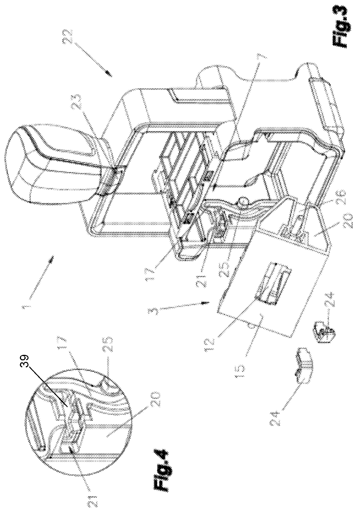
[0094]In FIGS. 1-24, a stamp 1, in particular a self-inking stamp 1 is shown, comprising at least one stamping component 2 and one stamping insert 3.

[0095]The stamping component 2 consists at least of a top part 4 having a handle element 5 and a bottom part 6 with a cushion-receiv...


PUM


Abstract

In some embodiments, a stamp may comprise at least one stamping component and one stamping insert. The stamp component may be formed of a top a bottom part with a cushion-receiving element. The stamping insert may be connected so as to move synchronously via a reversing mechanism having a slide track in the bottom part via an shaft or trunnion to the top part. In the resting position a text plate mounted on the stamping insert may abut against an ink pad in the cushion receiving element, and that in a stamping process the stamping insert with the text plate can be shifted by the reversing mechanism into a stamping position. At least the text plate carrier and / or the mounted band unit or date unit, may be positioned to be replaceable with the shaft or the trunnions or stub shafts, respectively. The system may include a stamping insert.

Description

PRIORITY CLAIM[0001]This application claims priority to Austrian Patent Application No. A50473 / 2015 entitled “Individualisierung” filed on Jun. 10, 2015, all of which is incorporated by reference herein.BACKGROUND OF THE INVENTION[0002]1. Field of the Invention[0003]The invention relates to a stamping device or, as it is hereinafter generally referred to, stamp, and a stamping insert, in particular as a replacement part for a stamp.[0004]2. Description of the Relevant Art[0005]From EP 0804344 B1, a stamping device with top inking, also known as self-inking stamp, is known that has a receiving frame made of metal for a stamping insert, which is guided in lateral parts of the receiving frame. The receiving frame supports a bottom part made of plastic. The stamping insert is adjustable via a reversing mechanism from a resting position, in which ink is adsorbed from a cushion placed in an ink pad, to an imprinting position against a spring force by a bow-shaped top part. The bow-shaped ...

Claims


Application Information

Patent Timeline
Patent Type & Authority Patents(United States)
IPC IPC(8): B41K1/04B41K1/40B41K1/42B41K1/56B41K1/38
CPCB41K1/04B41K1/56B41K1/42B41K1/38B41K1/40B41K1/10B41K1/36
Inventor SCHARINGER, HERBERTLEIBEZEDER, REINHARDLINDNER, HELMUT
Owner TRODAT GMBH
Why Eureka
Try Eureka