Control device for compression-ignition engine

a control device and compression ignition technology, applied in the direction of electric control, combustion engines, machines/engines, etc., can solve the problems of increased engine load, increased engine load, and difficult control during a transient operation, so as to improve the thermal efficiency of partial compression ignition combustion and secure combustion stability

Active Publication Date: 2020-10-06
MAZDA MOTOR CORP
View PDF15 Cites 4 Cited by
  • Summary
  • Abstract
  • Description
  • Claims
  • Application Information

AI Technical Summary

Benefits of technology

[0006]The present disclosure is made in view of the above situations and aims to provide a control device for a compression-ignition engine, which suitably secures combustion stability while improving thermal efficiency in partial compression-ignition combustion as much as possible.
[0008]According to this configuration, when it is confirmed during the partial compression-ignition combustion that the combustion stability is low, the A / F controller is controlled to reduce the air-fuel ratio (A / F) inside the cylinder. Accordingly, a rich fuel environment is formed inside the cylinder which stimulates a formation of flame core after the spark ignition. Thus, a sufficient size of flame core is stably formed and, as a result, the stability of the partial compression-ignition combustion is improved.
[0009]In other words, since the high air-fuel ratio is maintained unless the combustion stability drops, a period of the partial compression-ignition combustion is performed in a lean fuel environment, which is advantageous in terms of thermal efficiency, is secured as long as possible, and fuel efficiency of the engine is effectively improved.
[0014]The combustion controller may select, as a combustion mode of the partial compression-ignition combustion, one of a first mode in which the partial compression-ignition combustion is performed in an environment in which the air-fuel ratio is higher than a stoichiometric air-fuel ratio and a second mode in which the partial compression-ignition combustion is performed in an environment in which a gas-fuel ratio is higher than the stoichiometric air-fuel ratio and the air-fuel ratio is substantially the stoichiometric air-fuel ratio, and when it is confirmed during the partial compression-ignition combustion in the first mode, that the combustion stability is low, the combustion controller may switch the combustion mode from the first mode to the second mode, the gas-fuel ratio being a ratio of a total gas including EGR (exhaust gas recirculation) gas to fuel inside the cylinder.
[0015]According to this configuration, when the combustion stability is high, the first mode is selected and the partial compression-ignition combustion is performed in the lean fuel environment in which the air-fuel ratio (A / F) inside the cylinder is high. On the other hand, when the combustion stability drops while the first mode is selected, the combustion mode is switched from the first mode to the second mode and the partial compression-ignition combustion is performed in relatively rich fuel environment in which the air-fuel ratio is low. Thus, while the partial compression-ignition combustion in the first mode with high thermal efficiency is performed basically, when the combustion stability drops during the first mode selected, the combustion mode is switched to the second mode so as to promptly recover the combustion stability.
[0017]According to this configuration, since the combustion center of gravity does not largely deviate even when the combustion mode is switched between the first mode and the second mode, a change in torque when switching the mode (a difference in output torque before and after switching) is reduced, and a smooth mode switching which is not easily perceived by a passenger is achieved.

Problems solved by technology

However, the HCCI combustion has issues such as a combustion start timing of the mixture gas (a timing that the mixture gas self-ignites) greatly varying due to an external factor (e.g., atmospheric temperature) and a control during a transient operation in which an engine load sharply changes is difficult.
If the variation in the flame core formation state becomes large, the switching timing from the SI combustion to the CI combustion (a start timing of the CI combustion) greatly shifts either to the advancing or retarding side from a target timing and the combustion may become unstable.
When such unstable combustion continues, vibration, etc. in the engine increases and marketability of the engine drops.

Method used


Image

  • Control device for compression-ignition engine
  • Control device for compression-ignition engine
  • Control device for compression-ignition engine

Examples


Embodiment Construction

(1) Overall Configuration of Engine

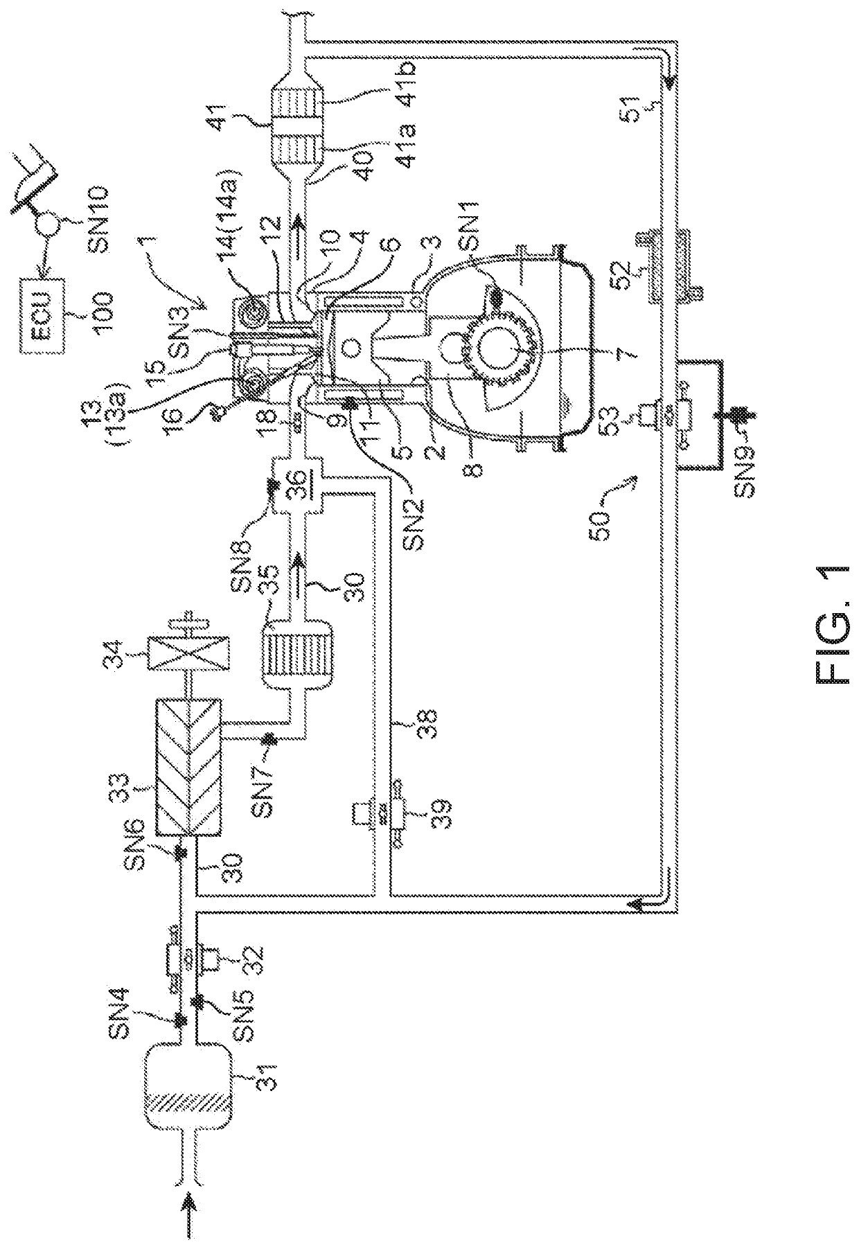
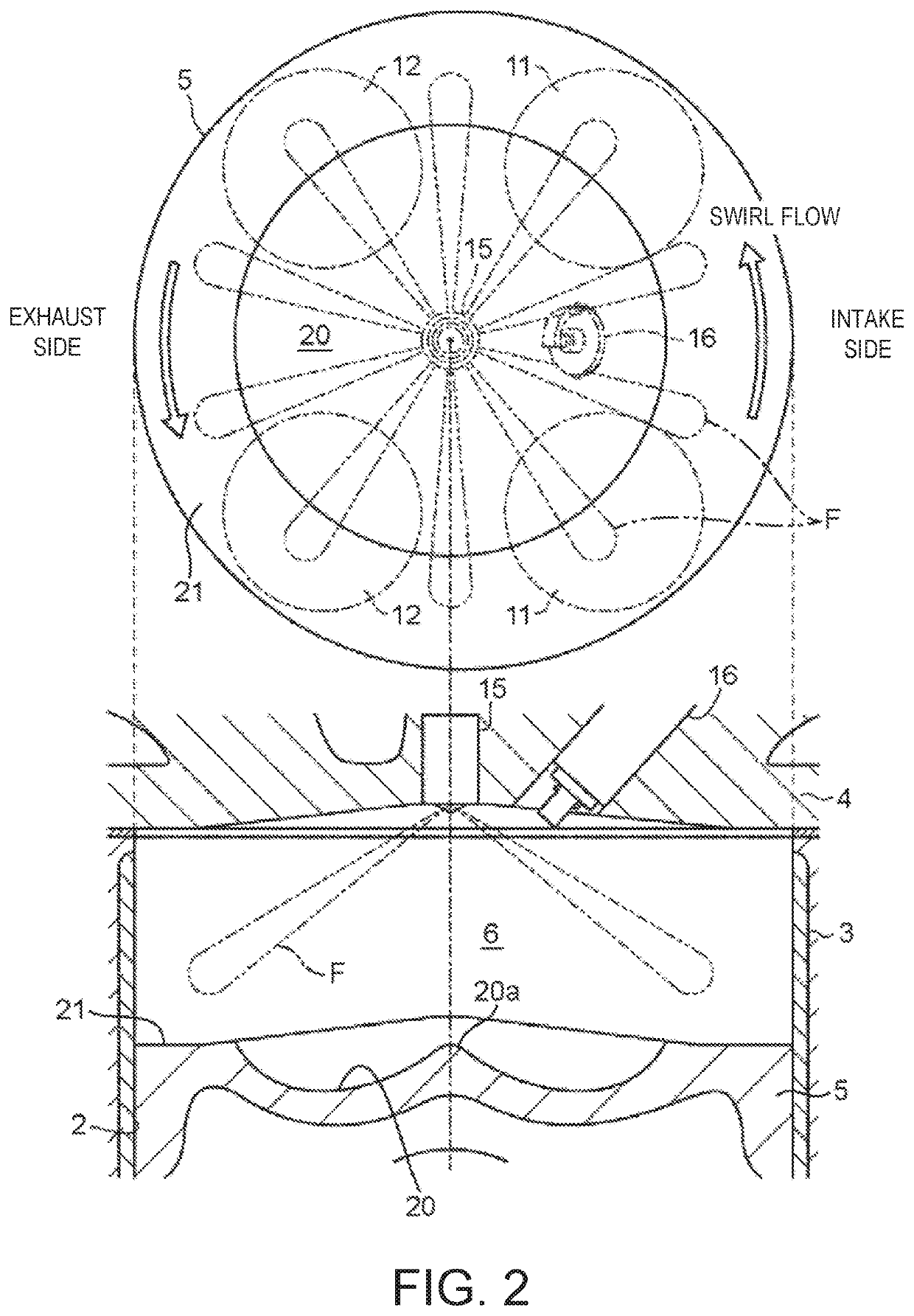
[0034]FIGS. 1 and 2 are diagrams illustrating a suitable embodiment of a compression-ignition engine (hereinafter, simply referred to as “the engine”) to which a control device of the present disclosure is applied. The engine illustrated in FIGS. 1 and 2 is a four-cycle gasoline direct-injection engine mounted on a vehicle as a drive source for traveling, and includes an engine body 1, an intake passage 30 through which intake air to be introduced into the engine body 1 flows, an exhaust passage 40 through which exhaust gas discharged from the engine body 1 flows, and an EGR device 50 which recirculates a portion of the exhaust gas flowing through the exhaust passage 40 to the intake passage 30.

[0035]The engine body 1 has a cylinder block 3 formed therein with cylinders 2, a cylinder head 4 attached to an upper surface of the cylinder block 3 so as to cover above the cylinders 2, and a piston 5 reciprocatably fitted into each cylinder 2. Typically,...


PUM


Abstract

A control device for a compression-ignition engine in which partial compression-ignition combustion including spark ignition (SI) combustion performed by combusting a portion of a mixture gas inside a cylinder by spark-ignition followed by compression ignition (CI) combustion performed by causing the remaining mixture gas to self-ignite is executed at least within a part of an engine operating range is provided, which includes a detector configured to detect a given parameter that changes as combustion progresses inside the cylinder, an A / F (air-fuel ratio) controller configured to change an air-fuel ratio of air to fuel introduced into the cylinder, and a combustion controller configured to determine combustion stability based on the detected parameter of the detector and control the A / F controller to reduce the air-fuel ratio when it is confirmed that during the partial compression-ignition combustion the combustion stability is low.

Description

TECHNICAL FIELD[0001]The present disclosure relates to a control device for a compression-ignition engine, which executes partial compression-ignition combustion in which a mixture gas within a cylinder is partially combusted by spark-ignition (SI combustion) and then the remaining mixture gas within the cylinder is combusted by self-ignition (CI (Compression Ignition) combustion).BACKGROUND OF THE DISCLOSURE[0002]Recently, HCCI (Homogeneous-Charge Compression Ignition) combustion in which gasoline fuel mixed with air is combusted by self-ignition inside a sufficiently compressed cylinder has attracted attention. The HCCI combustion is a mode in which a mixture gas combusts at a plurality of positions simultaneously, and thus has a higher combustion speed of the mixture gas than in SI combustion (spark-ignition combustion) which is adopted for general gasoline engines. Therefore, the HCCI combustion is said to be significantly advantageous in terms of thermal efficiency. However, th...

Claims


Application Information

Patent Timeline
Patent Type & Authority Patents(United States)
IPC IPC(8): F02D41/30F02D41/24F02D41/14F02D35/02F02D41/22F02D41/40F02B1/14F02D41/00
CPCF02D35/023F02D41/006F02D41/3064F02D41/1498F02B1/14F02D41/0057F02D35/028F02D41/2454F02D41/3041F02D41/402F02D41/3035F02D41/0087F02D2041/223F02D2041/0017Y02T10/40Y02T10/12
Inventor TANAKA, DAISUKETSUMURA, YUICHIROUJIHARA, KENKOHIGASHIO, MASAYOSHIMORIMOTO, HIROKI
Owner MAZDA MOTOR CORP
Why Eureka
Try Eureka