
Waveguide laser illuminator incorporating a despeckler

a waveguide laser and illuminator technology, applied in the field of illumination devices, can solve the problems of laser displays suffering from speckles, classical illumination designs using beam splitters and combiners fail to meet the requirements, and the demand for yet more compressed form factors continues unabated

Active Publication Date: 2020-06-02
DIGILENS
View PDF1524 Cites 29 Cited by
  • Summary
  • Abstract
  • Description
  • Claims
  • Application Information

AI Technical Summary

Benefits of technology

This patent is about a small laser that produces light without any unwanted spots. This is done by using a special device called a waveguide. The technical effect of this invention is to provide a more uniform and high-quality laser output for various applications.

Problems solved by technology

Although lasers offer much more compact illumination solutions than can be provided with conventional sources such as LED the demand for yet more compressed form factors continues unabated.
Classical illumination designs using beam splitters and combiners fail to meet the requirements.
Laser displays suffer from speckle, a sparkly or granular structure seen in uniformly illuminated rough surfaces.
Speckle reduces image sharpness and is distracting to the viewer.

Method used


Image

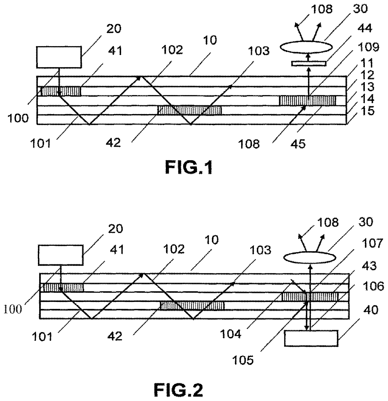
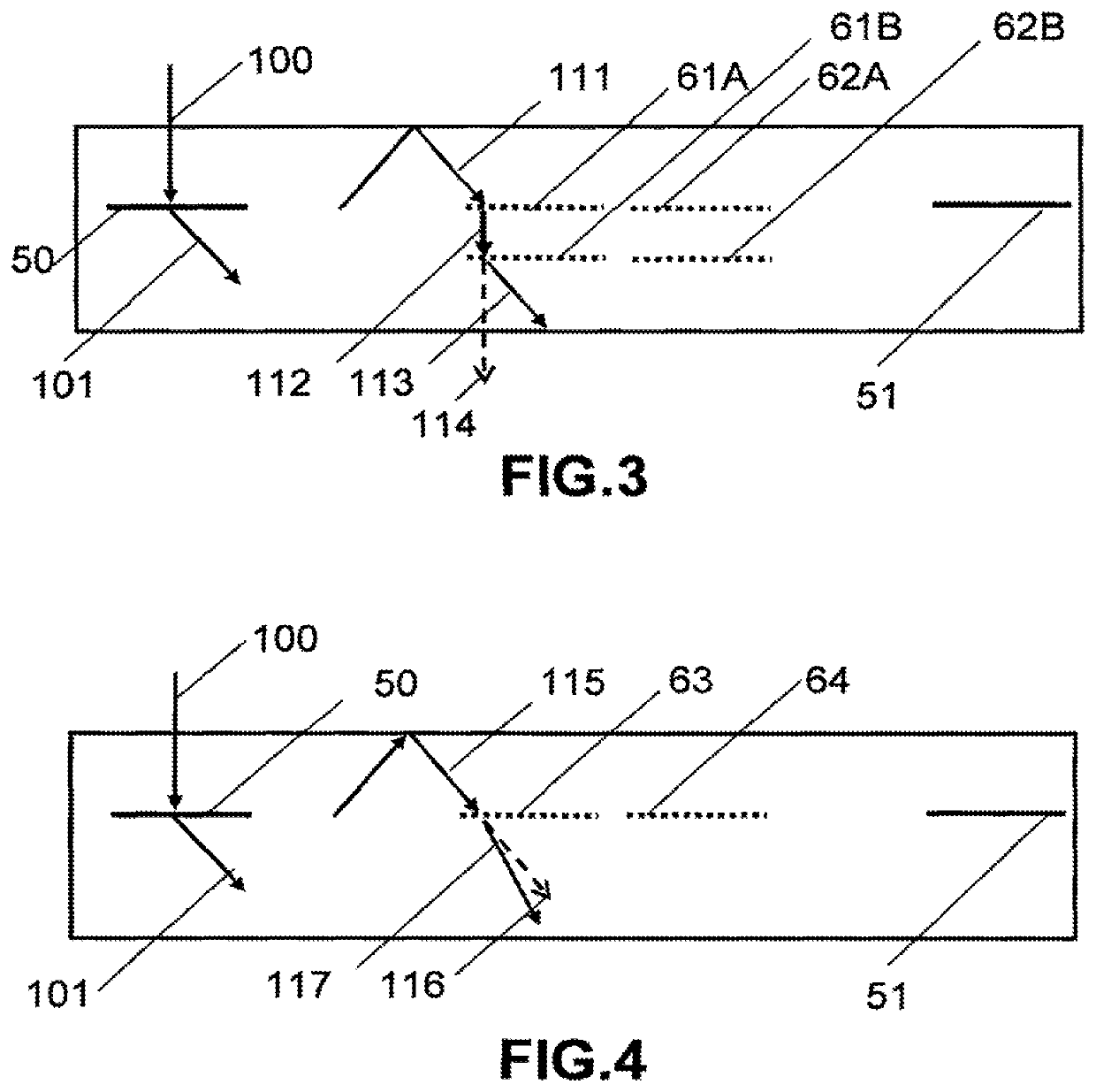
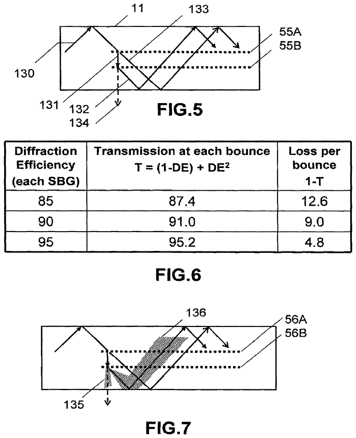
  • Waveguide laser illuminator incorporating a despeckler
  • Waveguide laser illuminator incorporating a despeckler
  • Waveguide laser illuminator incorporating a despeckler

Examples


Embodiment Construction

[0059]The invention will now be further described by way of example only with reference to the accompanying drawings.

[0060]It will apparent to those skilled in the art that the present invention may be practiced with some or all of the present invention as disclosed in the following description. For the purposes of explaining the invention well-known features of optical technology known to those skilled in the art of optical design and visual displays have been omitted or simplified in order not to obscure the basic principles of the invention.

[0061]Unless otherwise stated the term “on-axis” in relation to a ray or a beam direction refers to propagation parallel to an axis normal to the surfaces of the optical components described in relation to the invention. In the following description the terms light, ray, beam and direction may be used interchangeably and in association with each other to indicate the direction of propagation of light energy along rectilinear trajectories.

[0062...


PUM

PropertyMeasurementUnit
internal incidence angleaaaaaaaaaa
internal incidence anglesaaaaaaaaaa
thicknessaaaaaaaaaa

Abstract

There is provided an illumination device having: a laser; a waveguide including at least first and second transparent lamina; a first grating device for coupling light from the laser into a TIR path in the waveguide; a second grating device for coupling light from the TIR path out of the waveguide; and a third grating device for applying a variation of at least one of beam deflection, phase retardation or polarization rotation across the wavefronts of the TIR light. The first second and third grating devices are each sandwiched by transparent lamina.

Description

CROSS-REFERENCE TO RELATED APPLICATIONS[0001]This application is the U.S. national phase of PCT Application No. PCT / GB2015 / 000225 filed on Aug. 4, 2015, which claims the benefit of U.S. Provisional Patent Application No. 61 / 999,866 filed on Aug. 8, 2014, the disclosures of which are incorporated in their entirety by reference herein.BACKGROUND OF THE INVENTION[0002]The present invention relates to an illumination device, and more particularly to a laser illumination device based on electrically switchable Bragg gratings that reduces laser speckle.[0003]Miniature solid-state lasers are finding their way into a range of display applications. The competitive advantage of lasers results from increased lifetime, lower cost, higher brightness and improved colour gamut. Although lasers offer much more compact illumination solutions than can be provided with conventional sources such as LED the demand for yet more compressed form factors continues unabated. Classical illumination designs us...

Claims


Application Information

Patent Timeline
Patent Type & Authority Patents(United States)
IPC IPC(8): G02F1/29G02B27/48F21V8/00G02F1/313G02B5/32G02B27/42
CPCG02F1/292G02B6/0083G02B27/48G02B5/32G02B6/0055G02B6/0038G02B6/0016G02B27/4261G02F1/3136
Inventor POPOVICH, MILAN MOMCILOWALDERN, JONATHAN DAVIDGRANT, ALASTAIR JOHN
Owner DIGILENS
Learn More