
Method for manufacturing a sensor for a part of a piece of furniture

a manufacturing method and sensor technology, applied in the direction of furniture parts, wing accessories, pulse techniques, etc., to achieve the effect of efficient supply of parts

Active Publication Date: 2020-06-16
GRASS GMBH & CO KG
View PDF10 Cites 0 Cited by
  • Summary
  • Abstract
  • Description
  • Claims
  • Application Information

AI Technical Summary

Benefits of technology

[0005]The present invention is based on the object of efficiently providing a part of a piece of furniture with a space-saving sensor.
[0006]The present invention is based on a method for manufacturing a sensor for a part of a piece of furniture. The core of the present invention is that a layer, necessary for the actual sensor function, of the sensor is printed onto the part of the piece of furniture. A plurality of, in particular all of, the layers of the sensor are preferably printed onto the part of the piece of furniture. Advantageously efficient manufacturing is obtained by virtue of the fact that, in particular, the entire sensor is manufactured in such a way that one or more layers of the sensor are printed onto the part of the piece of furniture. A multiplicity of printing methods, for example, relief printing, flat printing and through-printing (for example, screen printing) which can be adapted advantageously to a wide range of requirements of the material of the sensor layer as well as the material and the shape of the part of the piece of furniture, in particular, an application point for the sensor, are known. In this context, printing onto a part of a piece of furniture can be carried out comparatively quickly. In particular if the sensor can be manufactured mostly or completely by printing on one or more layers, the method according to the present invention permits a part of a piece of furniture to be equipped efficiently with the sensor in one embodiment which is advantageously arranged inconspicuously on an outer side, in particular, a front side, of a part of a piece of furniture which can be viewed satisfactorily. Particularly when a part of a piece of furniture is produced in relatively large numbers, the method according to the present invention permits manufacturing costs for a part of a piece of furniture with a sensor to be advantageously reduced.

Problems solved by technology

However, if a layer such as, for example, a mounting layer or such as, for example, a color coating is selected for ensuring, for example, that an undesired or even disruptive influence of the part of the piece of furniture on the method of functioning of the sensor is screened, this is a layer which is necessary for the actual method of functioning.

Method used


Image

  • Method for manufacturing a sensor for a part of a piece of furniture
  • Method for manufacturing a sensor for a part of a piece of furniture

Examples


Embodiment Construction

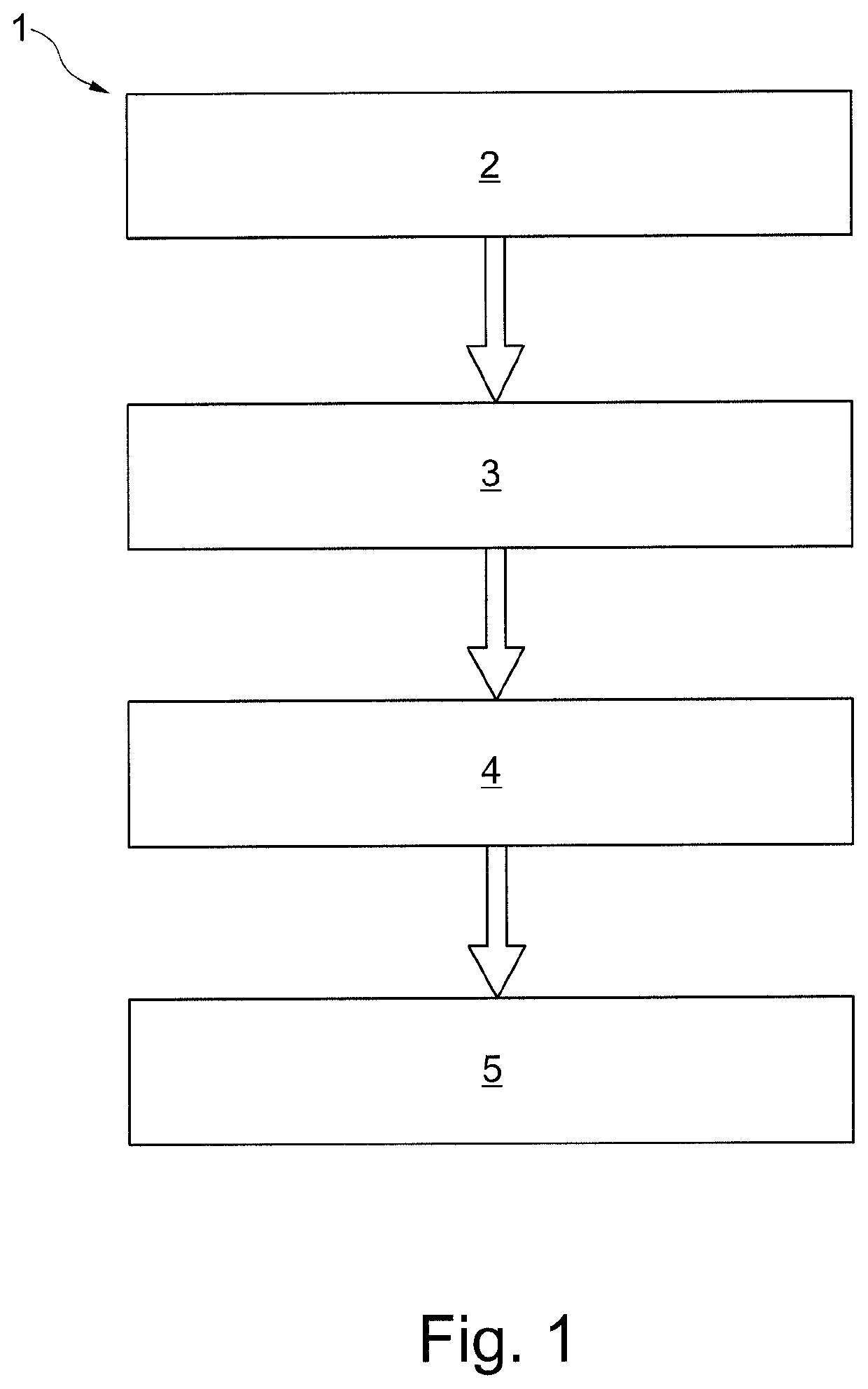
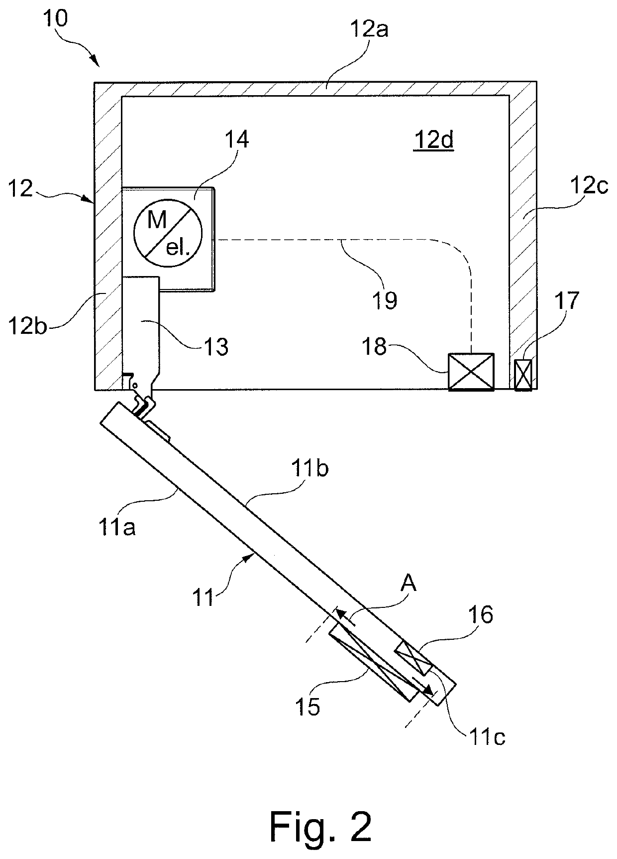
[0025]FIG. 1 shows an exemplary embodiment of a method 1 according to the present invention, in which a part 11 of a piece of furniture 10 is manufactured in four method steps 2, 3, 4 and 5. An exemplary embodiment of a piece of furniture 10 according to the present invention is shown in FIG. 2. The part 11 of the piece of furniture can be a component of a furniture carcass 12 or a movable part of a piece of furniture such as, for example, a door and, for example, a drawer.

[0026]In a first method step 2, the part 11 of the piece of furniture can be manufactured to such an extent that the part of the piece of furniture can be printed. The method step 2 can comprise a multiplicity of processing steps (not illustrated) with which the part 11 of the piece of furniture can mainly or completely be manufactured as far as its ultimate mechanical dimensions. For example, the method step 2 can have a processing step (not shown) in which the part of the piece of furniture is cut out as a blank...


PUM


Abstract

A method for manufacturing a sensor for a part of a piece of furniture is described, in which method a layer, necessary for the actual sensor function, of the sensor is printed onto the part of the piece of furniture. Furthermore, a corresponding sensor, a part of the piece of furniture, a switching device and a piece of furniture are presented.

Description

CROSS REFERENCE TO RELATED APPLICATIONS[0001]This application is a continuation of International Application No. PCT / EP2015 / 078445 filed Dec. 3, 2015, which designated the United States, and claims the benefit under 35 USC § 119(a)-(d) of German Application No. 10 2015 100 914.5 filed Jan. 22, 2015, the entireties of which are incorporated herein by reference.FIELD OF THE INVENTION[0002]The present invention relates to a method for manufacturing a sensor for a part of a piece of furniture and a sensor for a part of a piece of furniture, a part of a piece of furniture, a switching device and a piece of furniture.BACKGROUND OF THE INVENTION[0003]In the field of the construction of furniture, furniture is being increasingly equipped with electrical and electronic components in order to make its use, for example, easier, in particular, more convenient.[0004]Compared to mechanical devices for activating and driving, for example, movable parts of pieces of furniture such as, for example, ...

Claims


Application Information

Patent Timeline
Patent Type & Authority Patents(United States)
IPC IPC(8): A47B88/457E05F15/603E05F15/60A47B88/473A47B97/00H03K17/96E05F15/70B41M1/38
CPCB41M1/38E05F15/603A47B88/457A47B88/473E05F15/60A47B97/00E05F15/70H03K17/962A47B2220/0091E05Y2900/20E05Y2201/434E05Y2400/44E05Y2600/50
Inventor KRUEDENER, BORISHERPER, MARKUS
Owner GRASS GMBH & CO KG
Learn More