
Method for producing a negative cast for a brace with corrective forces to control PLC deficiencies

a technology of corrective force and negative cast, which is applied in the field of orthose, can solve the problems of not being able to achieve neutral or external foot rotation, and traditional methods do not produce the rotational alignment required

Active Publication Date: 2020-06-16
STUART WILLIAM
View PDF25 Cites 0 Cited by
  • Summary
  • Abstract
  • Description
  • Claims
  • Application Information

AI Technical Summary

Benefits of technology

The present invention provides methods for creating negative casts of human legs using advanced techniques. The methods involve positioning the leg with a bent knee at different angles, wrapping casting material around the leg, applying corrective forces to the knee, extending the knee, allowing the casting material to dry, and then removing the casting material from the leg. The technical effects of these methods include improved accuracy and stability of the negative cast, as well as reduced pain and discomfort for the patient during the casting process.

Problems solved by technology

The prior art has soft anterior shells, very narrow hard shells, or larger shells made from non-corrective casts, and do not extend proximally over the tibial condyles, not having corrective forces applied during casting or measuring.
It is also difficult or not possible to achieve neutral or external foot rotation with some patients with moderate to severe neuroskeletal deficits or deformities.
This traditional method does not produce the rotational alignment required to achieve the maximum benefit to the patient.
Even a cast taken with the external rotary deficiency (ERD) corrections to the foot does not affect the rotation of the knee adequately.

Method used


Image

  • Method for producing a negative cast for a brace with corrective forces to control PLC deficiencies
  • Method for producing a negative cast for a brace with corrective forces to control PLC deficiencies
  • Method for producing a negative cast for a brace with corrective forces to control PLC deficiencies

Examples


Embodiment Construction

[0015]The description set forth below in connection with the appended drawings is intended as a description of presently preferred embodiments of the disclosure and is not intended to represent the only forms in which the present disclosure may be constructed and / or utilized. The description sets forth the functions and the sequence of steps for constructing and operating the disclosure in connection with the illustrated embodiments. It is to be understood, however, that the same or equivalent functions and sequences may be accomplished by different embodiments that are also intended to be encompassed within the spirit and scope of this disclosure.

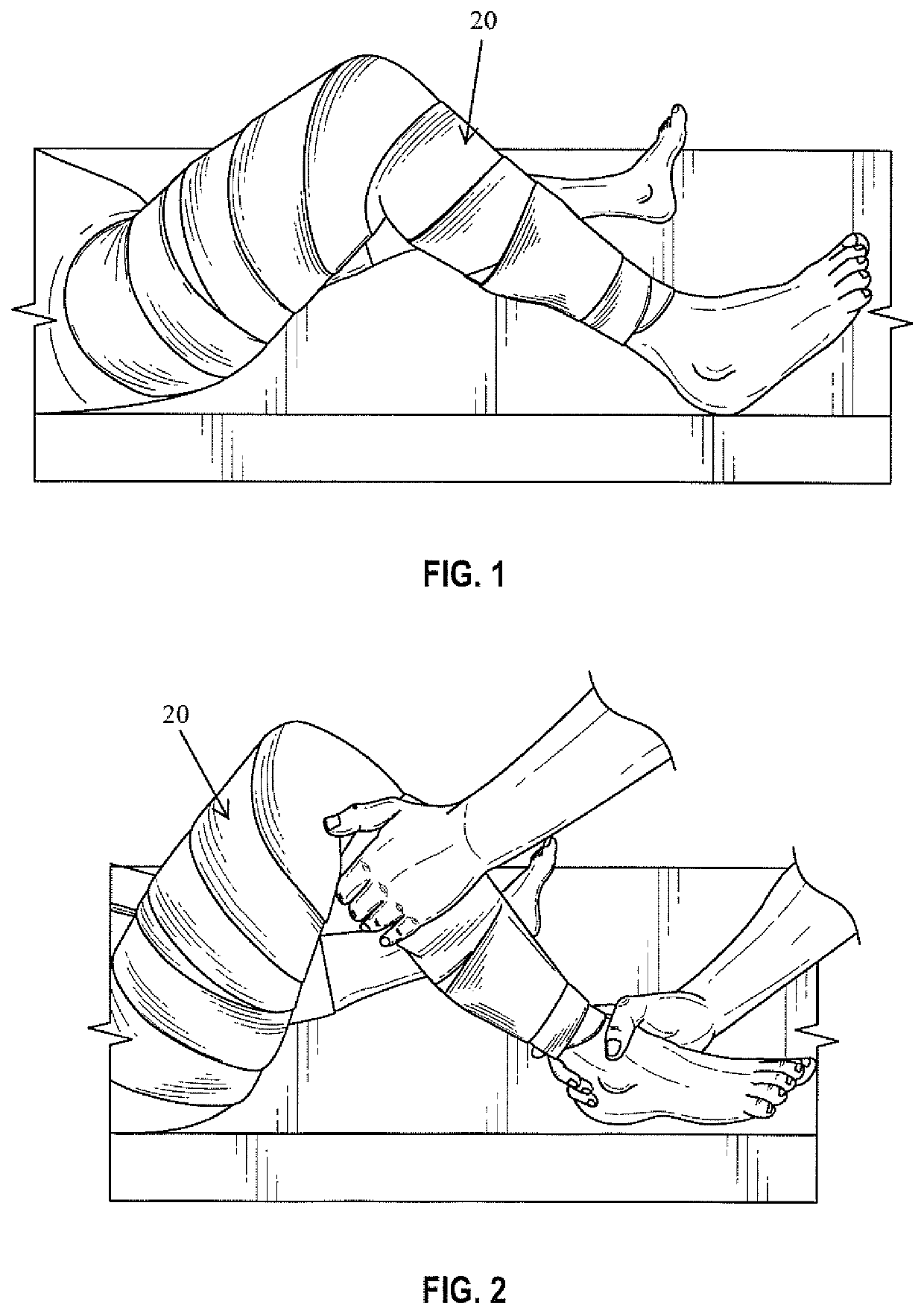
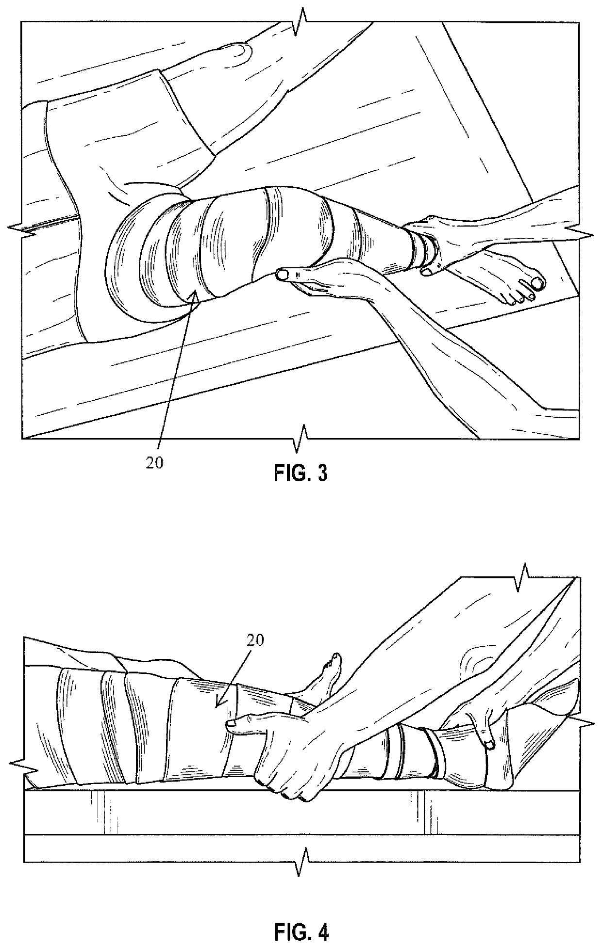
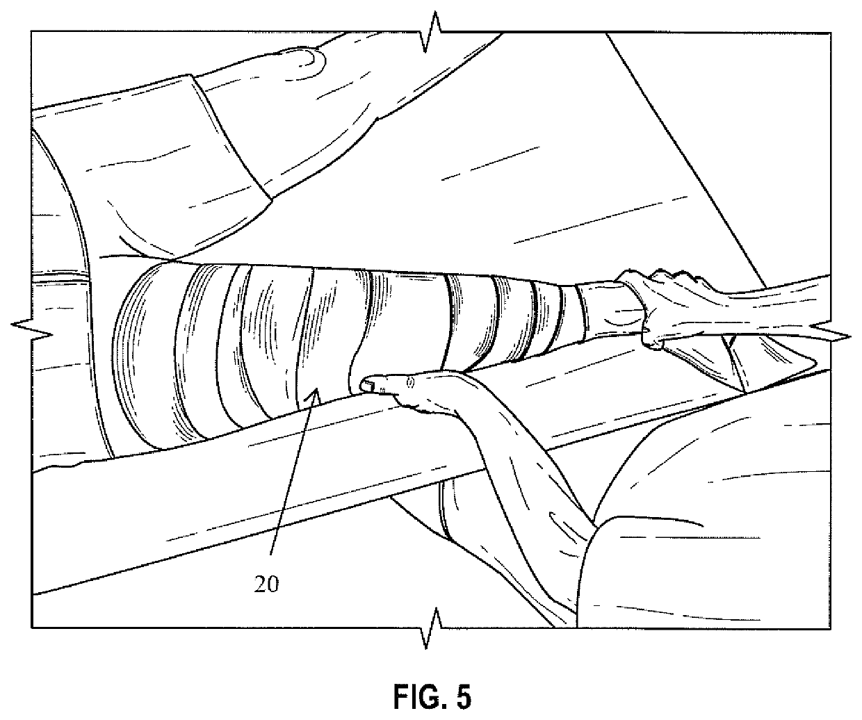
[0016]FIGS. 1-5, together, disclose the method for providing a negative cast to be used to fabricate the orthosis for a patient suffering from posterolateral corner deficit. The present invention provides innovative casting techniques applied during the process of producing a negative corrective cast which is an important component of the ...


PUM

PropertyMeasurementUnit
Angleaaaaaaaaaa
Angleaaaaaaaaaa
Angleaaaaaaaaaa

Abstract

A casting method for a brace having corrective forces is disclosed. The foot is externally rotated during casting and corrective forces are applied at the lateral knee and anteromedial ankle. With the knee flexed at between about 70° to 90°, the cast is fully extended, which places the knee in a position which will reduce the pressures on the medial knee. This is the position desired during the casting process with the knee flexed and then held while extending the knee. The result is control of the posterior lateral rotation, therefore controlling the posterior subluxation of the tibial plateau to achieve the motion and alignment that the screw home motion produces.

Description

FIELD OF THE INVENTION[0001]The present invention generally relates to orthoses and more specifically, a method for producing a negative cast for a brace with corrective forces to control PLC deficiencies.BACKGROUND OF THE INVENTION[0002]Orthoses are external supports (braces) for the body, which are custom fitted and / or custom fabricated for the specific needs of the patient. The typical process for creating a brace for a patient includes patient assessment, formulation of a treatment plan for the patient, implementation of the treatment plan, follow-up, and practice management.[0003]The procedures traditionally used to produce a knee orthosis (KO) only involve the use of measurements or creating a negative cast (which is wrapped on the patient). When the brace is produced from a cast, some manufacturers instruct practitioners to position the patient's knee in full extension without corrective forces applied during the procedure. The manufacturer then modifies the positive cast (by...

Claims


Application Information

Patent Timeline
IPC IPC(8): B28B1/40A61F5/01B28B7/34A61F2/50B29C33/38
CPCA61F5/0102B28B7/344A61F5/0106A61F5/0109B28B1/40A61F2240/004B29C2033/3871A61F2002/5053
Inventor STUART, WILLIAM
Owner STUART WILLIAM
Learn More