
Compression mold

a mold and compression technology, applied in the field of molds, can solve the problems of hard contact risk, drawbacks of the known mold described above, and thin bottom thickness d of the object to be formed

Active Publication Date: 2020-06-16
SACMI COOP MECCANICI IMOLA SOC COOP A R L
View PDF7 Cites 0 Cited by
  • Summary
  • Abstract
  • Description
  • Claims
  • Application Information

AI Technical Summary

Benefits of technology

[0019]Where the wet surfaces are surfaces of the forming cavity intended to contact the plastic during the forming phase, in accordance with embodiments of the present application, hard contact between the wet surfaces of the two half-molds also without plastics is avoided.
[0020]As mentioned above, in accordance with embodiments of the present invention, hard contact by the elastic and / or thermal deformation of the press structure on which the mold is assembled is avoided. Particularly, the above-mentioned hard contact is avoided regardless of the elasticity of the press structure.
[0021]In accordance with embodiments of the present invention, any deformation (thermal and / or elastic) of the press body, or of other elements external to the mold, will not affect the precision of the dimension defining the thickness of the object wall, particularly because that precision will be dependent on a tolerance chain that is internal to each single mold.
[0025]In accordance with embodiments of the present invention the compression assembly is able to obtain the desired thickness of the bottom wall of the molded object even when the mold is supplied with a plastic dose having an insufficient or abundant volume.
[0026]Even after the relatively thin bottom wall of the object in the forming cavity is already solidified, in accordance with embodiments of the present application, transmission of the compression forces compensates for the shrinkage of the plastic material.
[0032]In accordance with embodiments of the present invention, the development of plastic material splinters during breaking phase of the weak portion is avoided.

Problems solved by technology

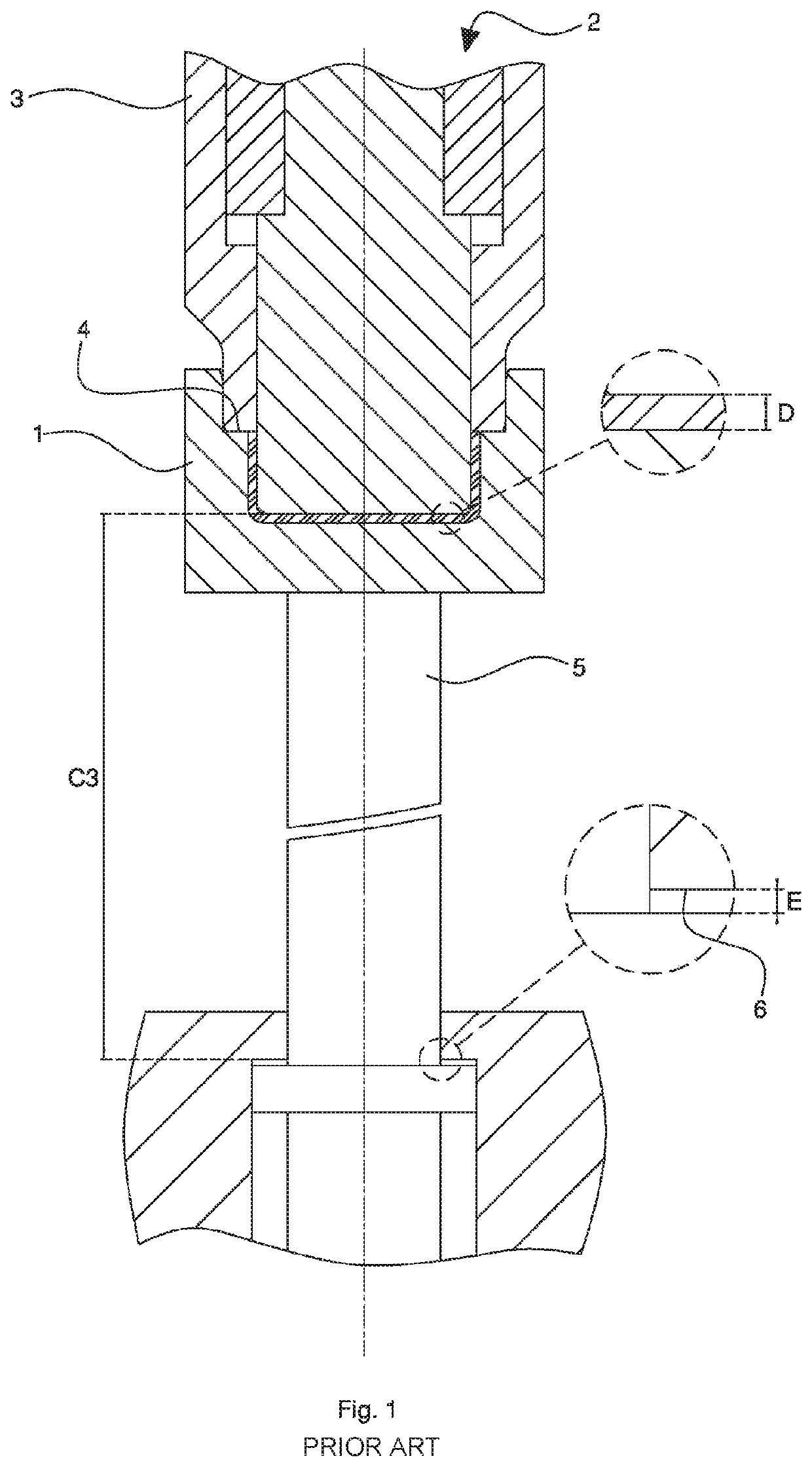
One of the drawbacks of the known mold described above can be seen when the bottom thickness D of the object to be formed is very thin.
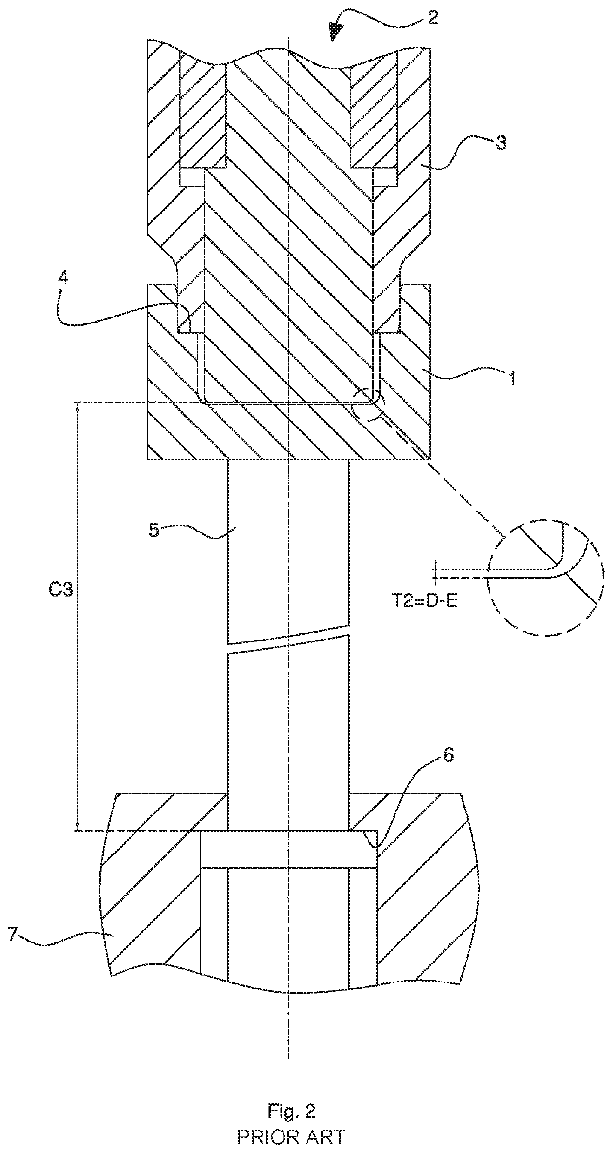
This results in a hard contact risk, or in an excessive distance between the “wet” surfaces of the two reciprocally facing half-molds when the empty mold closes, without plastics, where with wet surfaces it is intended for the forming cavity surfaces to contact the plastics during the forming phase.
This hard contact can result in a collision between the two half-molds during the closure phase, causing considerable damage to the mold.
The risk is increased when the press is formed by a complex apparatus, such as for example a forming carousel which rotates a plurality of molds, because in this case the precision of the distance T2 with an empty mold would inevitably be very poor as it would depend on a long chain of dimensional tolerances going through the forming carousel.
The deviation of the real dimension from the nominal dimension T2, generally different from mold to mold, could be excessive for at least one or more molds, leading to the hard contact.
Practically, in the compression molding carousel for doses of plastic material of a known type, it is not possible to mold objects (caps) having a bottom with nominal thickness lower than about 0.2-0.3 millimeters.
Therefore, the compression mold shown by U.S. Pat. No. 6,736,628 could show the risk of hard contact between the two half-molds during the closure phase without plastics, especially when the bottom thickness of the object to be formed is very thin.
In the mold of FIG. 4, a closed position without plastic where the forming cavity volume is less than the closed position with plastic would be unacceptable, because in this closed position with plastic—being purely hypothetical and totally unsuitable—the collar 60 and the element 82 will inevitably lose contact from each other, with the devastating effect of the injected plastic coming out from the forming cavity, which therefore will not be able to be considered as effectively closed.
Moreover it should be noticed that in case the thickness of one wall (for example the bottom) of the object to be formed is very thin, the flow sections for the fluid plastic are very narrow, making it extremely difficult for the plastic to flow.
Consequently, as a practical matter, injection molding is totally unsuitable to form very thin walls, unless extremely fluid plastics are used, resulting in a limitation of the application field.

Method used


Image

  • Compression mold
  • Compression mold
  • Compression mold

Examples


Embodiment Construction

[0066]In this description, similar elements in common with different mold examples illustrated in the FIGS. 1 to 12 have been shown with the same numbers and similar elements in common with different examples of cap bodies illustrated in FIGS. 13 to 30 have been shown with the same numbers.

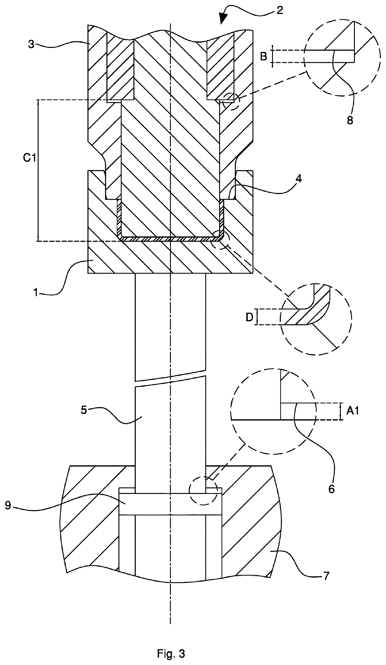
[0067]Referring to the FIGS. 3 and 4, a mold example for compression molding doses of plastic material according to an embodiment of the invention is illustrated. The mold includes a first (lower) half-mold 1 and a second (upper) half-mold 2 being axially movable (with vertical X axis) towards each other in order to assume an open position (not shown) in which it is possible to insert at least one dose of plastic material (coming from an extruder) between the above-mentioned half-molds and a non-end closed position (FIG. 3) or closed position with a dose, in which the dose of plastic material (in the pasty state) can be pressed in a cavity at least partially defined by the above-mentioned half-mol...


PUM

PropertyMeasurementUnit
distanceaaaaaaaaaa
distance T1aaaaaaaaaa

Abstract

A mold is provided for forming caps for closing containers by compression molding doses of plastic material, where a bottom wall of the cap, or at least one portion of the bottom wall is very thin. The mold includes two half-molds axially movable towards each other which assume an end closed position without a dose. A tubular element is slidable around the second half-mold and partially defines the cavity. The tubular element contacts an axial abutment of the first half-mold at one side and an axial end stop of the second half-mold at the other side to prevent hard contact between the half-molds.

Description

CROSS-REFERENCE TO EARLIER APPLICATION[0001]This application is a § 371 National Stage Entry of PCT / IB2016 / 050263 filed Jan. 20, 2016 entitled “Compression Mold.” PCT / IB2016 / 050263 claims priority to IT-MO2015A000016 filed Jan. 30, 2015. The entire content of these applications are herein incorporated by reference in their entirety.BACKGROUND OF THE INVENTION[0002]The invention concerns a mold, particularly a mold for press forming doses of plastic material being separated from an extruder.[0003]Specifically, but not exclusively, the invention can be applied to form plastic caps, for example to close containers.[0004]The prior art includes the mold of FIGS. 1 and 2 which are suitable for compression molding plastic material doses. This mold of a known type includes a first half-mold 1 (lower matrix) and a second half-mold 2 (upper punch) being axially movable towards one each other in order to assume at least one open position (not shown) and at least one non-end closed position (FI...

Claims


Application Information

Patent Timeline
Patent Type & Authority Patents(United States)
IPC IPC(8): B29C43/54B29C43/58B29C37/00B29C43/36B29C43/08B29L31/56
CPCB29C43/08B29C43/54B29C43/361B29C43/36B29C2037/94B29C2043/585B29L2031/565B29C43/58
Inventor BERGAMI, STEFANOPENAZZI, DAVIDE
Owner SACMI COOP MECCANICI IMOLA SOC COOP A R L
Learn More