Sensor device and method for carrying out or boosting an autonomous build-up of brake pressure in a braking system with the aid of an active brake booster

a technology of a sensor device and a braking system, which is applied in the direction of brake action initiation, foot actuation initiation, vehicle components, etc., can solve the problems of at least one braking system component being damaged, the extending object being struck and/or jammed, and the damage to the active brake booster

Active Publication Date: 2020-04-07
ROBERT BOSCH GMBH
View PDF15 Cites 0 Cited by
  • Summary
  • Abstract
  • Description
  • Claims
  • Application Information

AI Technical Summary

Benefits of technology

[0004]The present invention creates reliable options for early detection of a brake pedal blockage during an autonomous or partially autonomous brake pressure buildup in at least one wheel brake cylinder of a braking system. Due to the early detection of the brake pedal blockage, measures may still be carried out promptly with the aid of which a hard stop and / or jamming of an object by the brake pedal is / are preventable. Furthermore, since it is possible to reliably prevent a hard contact between the object and the brake pedal when using the present invention, there is also no need to fear damage to the braking system due to a reaction of the hard contact to the braking system, specifically to the active brake booster. The present invention thus contributes toward an increase in the safety of vehicle occupants, toward an improvement in object protection of objects present in the vehicle and to preservation of braking system components during the autonomous or partially autonomous brake pressure buildup.
[0006]In an advantageous specific embodiment, the at least one first control signal is outputtable to the active brake booster with the aid of the electronic device, the electronic device additionally being configured to output at least one second control signal to at least one valve of the braking system and / or at least one pump of the braking system during output of the at least one first control signal, the at least one valve and / or the at least one pump being activatable with the aid of the at least one second control signal in such a way that the autonomous brake pressure buildup is boostable with the aid of the at least one valve and / or the at least one pump, at least for the predefined first time interval, or at least being continuable for the predefined second time interval. Thus despite an impairment of the operation of the active brake booster (at least temporarily) triggered with the aid of the at least one first control signal, the autonomous brake pressure buildup may still be carried out reliably.
[0009]The electronic device is optionally configured to establish the at least one normal value range, taking into account at least the differential travel and / or the temporal change of the differential travel. The reliability of the comparison described above may be further increased in this way.
[0012]An active brake booster for a braking system which is configured for carrying out or boosting an autonomous or partially autonomous brake pressure buildup and includes such a control also creates the advantages described above.

Problems solved by technology

Since during an autonomous or partially autonomous brake pressure buildup carried out with the aid of the active brake booster, the brake pedal is generally also adjusted (despite not being operated by a driver) so there is traditionally the risk that the extending object might be struck and / or jammed.
Furthermore, a tensile force exerted onto the brake pedal by the jammed object and directed against the joint adjustment movement may result in damage to at least one braking system component, in particular damage to the active brake booster.

Method used


Image

  • Sensor device and method for carrying out or boosting an autonomous build-up of brake pressure in a braking system with the aid of an active brake booster
  • Sensor device and method for carrying out or boosting an autonomous build-up of brake pressure in a braking system with the aid of an active brake booster
  • Sensor device and method for carrying out or boosting an autonomous build-up of brake pressure in a braking system with the aid of an active brake booster

Examples


Embodiment Construction

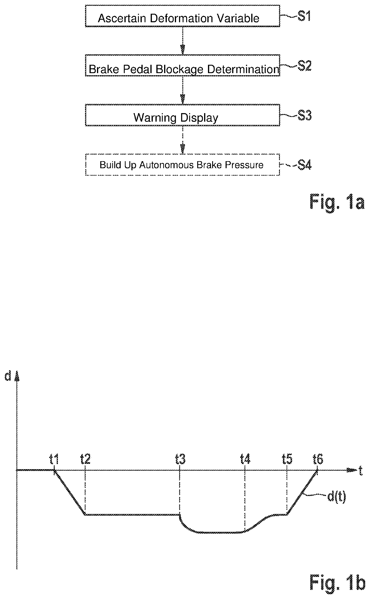
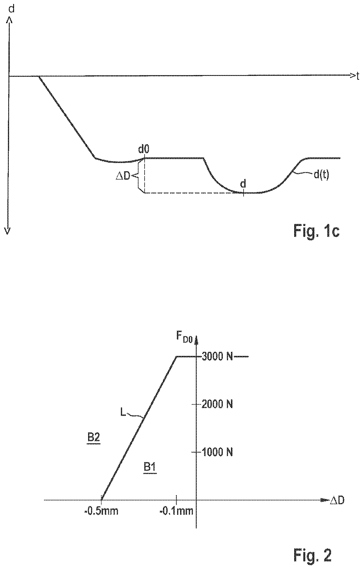
[0018]FIGS. 1a through 1c show a flow chart and coordinate systems for explaining a first specific embodiment of the method for carrying out or boosting an autonomous or partially autonomous brake pressure buildup in a braking system with the aid of an active brake booster.

[0019]The active brake booster used for carrying out the method may be understood to be a brake booster, with the aid of which an autonomous brake pressure buildup in at least one wheel brake cylinder of the respective braking system may be effectuated. The autonomous brake pressure buildup may also be referred to as an automatic brake pressure buildup, a power braking and / or a brake pressure buildup without actuation of a brake pedal of the respective braking system by a driver. It is pointed out that the autonomous brake pressure buildup takes place without initiation of a driver braking force in a main brake cylinder of the braking system and / or in the at least one wheel brake cylinder connected thereto. The au...


PUM


Abstract

A sensor device, active brake booster, and method for a braking system, including an active brake booster for carrying out / boosting an autonomous or partially autonomous brake pressure buildup, including an electronic device, which, at least during the autonomous or partially autonomous brake pressure buildup by the active brake booster, is configured, based on at least one deformation variable, provided externally or established by the sensor device, as to a deformation of the active brake booster, and / or a tensile force which effectuates the deformation and is exerted on a brake pedal, to output at least one activation signal to a warning display device and / or to a warning sound output device and / or at least one control signal to the active brake booster, to control the latter at least for a predefined first time interval into a safety mode or to interrupt the latter at least for a predefined second time interval.

Description

FIELD OF THE INVENTION[0001]The present invention relates to a sensor device for a braking system including an active brake booster configured for carrying out or boosting an autonomous or partially autonomous brake pressure buildup. Likewise, the present invention relates to an active brake booster. In addition, the present invention relates to a method for carrying out or boosting an autonomous brake pressure buildup in a braking system with the aid of an active brake booster.BACKGROUND INFORMATION[0002]An active brake booster may be understood to be a brake booster configured for carrying out or boosting an autonomous or partially autonomous brake pressure buildup. From the related art, there is a known plurality of active brake boosters such as, for example, electromechanical brake boosters. For example, DE 103 27 553 A1 discusses an electromechanical brake booster including a hollow shaft electric motor and a spindle gear with the aid of which a booster force may be exerted on ...

Claims


Application Information

Patent Timeline
Patent Type & Authority Patents(United States)
IPC IPC(8): B60T13/74B60T7/06B60T7/04B60T8/40
CPCB60T13/746B60T8/4077B60T7/042B60T7/065B60T13/743B60T13/745
Inventor SERRANO, DAVID RUBIALOPEZ, EDUARDO HERRERAGERDES, MANFREDZIEGLER, PETER
Owner ROBERT BOSCH GMBH
Why Eureka
Try Eureka