Pixel Unit Structure of Self-Illumination Display with Low-Reflection

a self-illumination display and unit structure technology, applied in the direction of basic electric elements, electrical apparatus, semiconductor devices, etc., can solve the problem of reducing the reflection of external environment light, and achieve the effect of reducing the amount of external environment light to the non-illuminative region of the first substrate, improving contrast performance, and improving illumination efficiency

Active Publication Date: 2009-10-22
AU OPTRONICS CORP
View PDF10 Cites 0 Cited by
  • Summary
  • Abstract
  • Description
  • Claims
  • Application Information

AI Technical Summary

Benefits of technology

[0009]Another purpose of the present invention is to provide a pixel unit structure of a self-illumination display which has better contrast performance.
[0010]The other purpose of the present invention is to provide a pixel unit structure of a self-illumination display which has a better utilizing rate for the illumination.
[0011]The pixel unit structure of the self-illumination display includes a first substrate, a light-absorbing structure, a filter layer, a driving circuit and a self-illumination unit. The first substrate is used to be the base board of the display panel and includes an illuminative region and a non-illuminative region. The light-absorbing structure is formed over the first substrate and disposed within the non-illuminative region. By the installation of the light-absorbing structure, the amount of the external environment light to the non-illuminative region of the first substrate is reduced. Therefore, the reflective light caused by the external environment light reflected from the circuit or the electronic components is reduced.
[0012]The filter layer is disposed over the first substrate and close to the light-absorbing structure. Because of the isolation of the filter layer, the amount of the external environment light emitted into the first substrate is reduced and the contrast of the image shown on the self-illumination display is enhanced. The driving circuit is disposed over the light-absorbing structure and sheltered by the light-absorbing structure. In other words, the external environment light emitted into the first substrate is hard to contact with the driving circuit components. Therefore, the probability that the external environment light reflected from the driving circuit or the metal material thereof is reduced.
[0013]The self-illumination unit is disposed over the filter layer and substantially corresponding to the illuminative region of the first substrate. The self-illumination unit includes a light-transmissible electrode layer, a light emitting layer and a black electrode layer. The light-transmissible electrode layer is formed over the filter layer and is made of the light-transmissible and conductive material. The light emitting layer and the black electrode layer are sequentially formed over the light-transmissible electrode layer. Because the reflection of the black electrode layer is lower than the common metal electrode, the reflective light generated by the black electrode layer is lower than the reflective light generated by the common metal electrode when the external environment light emits into the black electrode layer through the first substrate and the filter layer. When the reflective light is reduced, the light generated by the self-illumination unit is able to enhance the contrast of the image. Besides, by the installation of the light-absorbing structure, the filter layer and the black electrode layer, it is more efficient to reduce the amount of the reflective light generated by the external environment light and the contrast of the display device is enhanced.

Problems solved by technology

Therefore, how to reduce the reflection of the external environment light is the main issue in the development of the display panel.

Method used


Image

  • Pixel Unit Structure of Self-Illumination Display with Low-Reflection
  • Pixel Unit Structure of Self-Illumination Display with Low-Reflection
  • Pixel Unit Structure of Self-Illumination Display with Low-Reflection

Examples


Embodiment Construction

[0020]A pixel unit structure of a self-illumination display is disclosed in the present invention. In the preferred embodiment, the self-illumination display of the present invention is a color organic light emitting diode (OLED) display. In a different embodiment, the self-illumination display of the present invention is a monochromatic OLED display. Besides, in other embodiment, the self-illumination display of the present invention is a polymer light emitting diode (PLED) display. The self-illumination display of the present invention can be used in any display panels, home used flat panel TV, flat panel monitor for desktop or laptop, or display screen for mobile phone or digital camera.

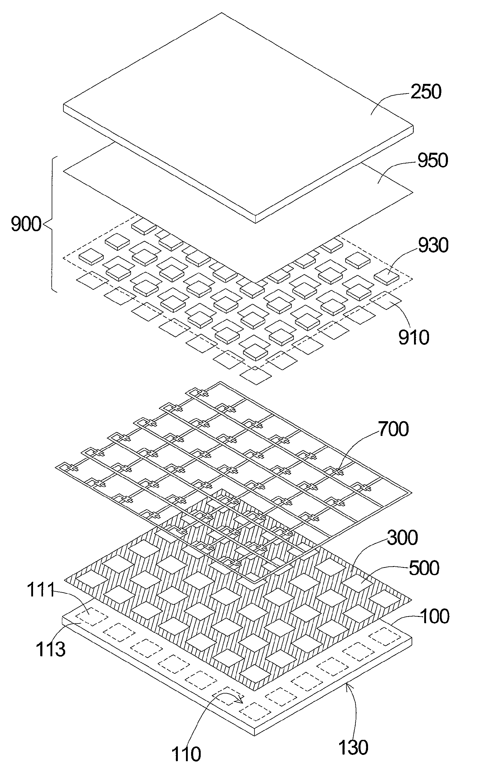
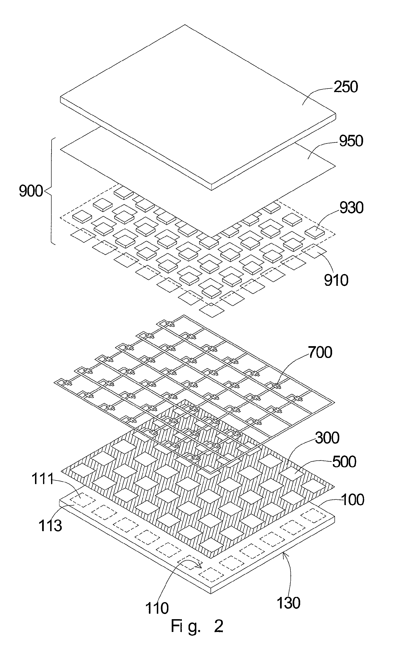
[0021]As the preferred embodiment shown in FIG. 2, the pixel unit structure of the self-illumination display includes a first substrate 100, a light-absorbing structure 300, a filter layer 500, a driving circuit 700, a self-illumination unit 900 and a backside substrate 250. In the present embodim...


PUM


Abstract

A self-illumination display is provided, including a first substrate, a light-absorbing structure, a filter layer, a driving circuit unit, and a self-illumination unit. The light-absorbing structure and the filter layer are juxtaposedly disposed over the first substrate. The driving circuit unit is disposed over and shielded by the light-absorbing structure. The self-illumination unit is disposed over the filter layer, including a light-transmissible electrode, a light emitting layer, and a black electrode. The self-illumination unit is disposed over the filter layer, including a light-transmissible electrode, a light emitting layer, and a black electrode. The light-transmissible electrode is disposed over the filter layer while the light emitting layer and the black electrode are sequentially tiered on the light-transmissible electrode. The light-absorbing structure, the filter layer and the black electrode together reduce the reflection of the ambient light and enhance the image contrast.

Description

CROSS-REFERENCES TO RELATED APPLICATIONS[0001]This application is a divisional of application Ser. No. 11 / 668,056, filed on Jan. 27, 2007, which is incorporated herein by reference.BACKGROUND OF THE INVENTION[0002]1. Field of the Invention[0003]The present invention generally relates to a pixel unit structure of a self-illumination display, and more particularly to a pixel unit structure of a self-illumination display with low-reflection.[0004]2. Description of the Prior Art[0005]As the purchasing demand of the slim displays increases day after day, the development of the self-illumination display technique is become more and more important. The technique of the self-illumination display, such as organic light emitting diode (OLED), is now well developed. For example, for the organic light emitting diode, the illumination of the display panel is the main consideration to determine whether the display device is good or not. In the display field, how to efficiently increase the utiliz...

Claims


Application Information

Patent Timeline
Patent Type & Authority Applications(United States)
IPC IPC(8): H01L29/04
CPCH01L27/3244H01L51/5284H01L29/78633H10K59/12H10K50/865
Inventor LEE, CHUNG-CHUN
Owner AU OPTRONICS CORP
Why Eureka
Try Eureka