
Pneumatic tire tread

a pneumatic tire and tread technology, applied in special tyres, vehicle components, transportation and packaging, etc., can solve the problems of reduced operating safety on wet road surfaces, reduced air column resonance noise, and increased so as to reduce the noise of air column resonance and ensure water drainage performance.

Inactive Publication Date: 2015-12-08
MICHELIN & CO CIE GEN DES ESTAB MICHELIN +1
View PDF10 Cites 0 Cited by
  • Summary
  • Abstract
  • Description
  • Claims
  • Application Information

AI Technical Summary

Benefits of technology

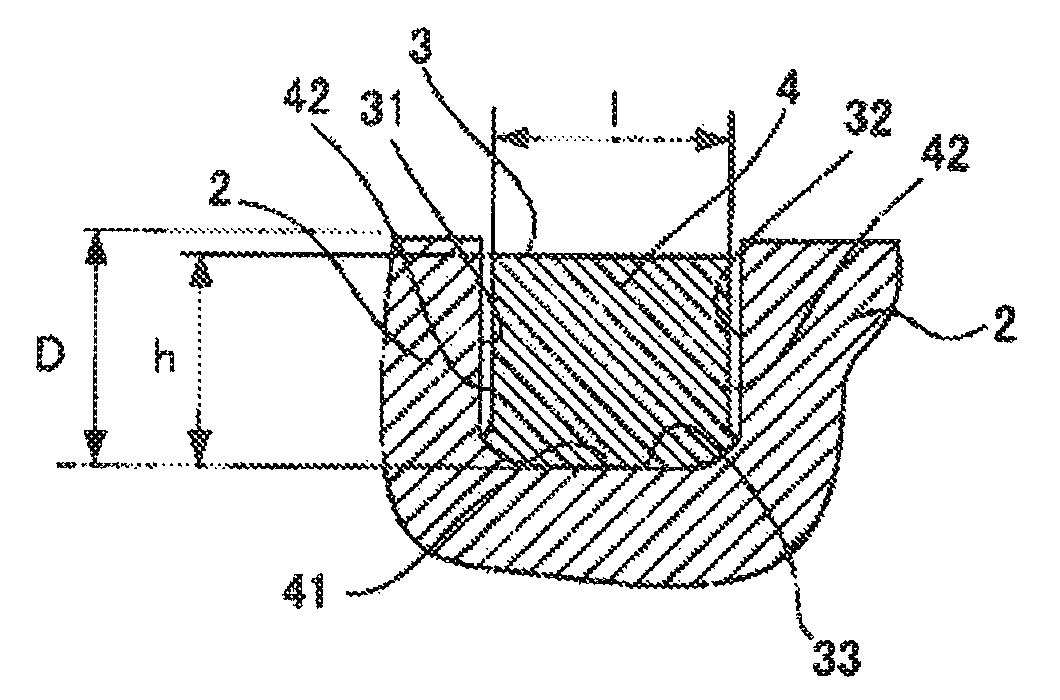
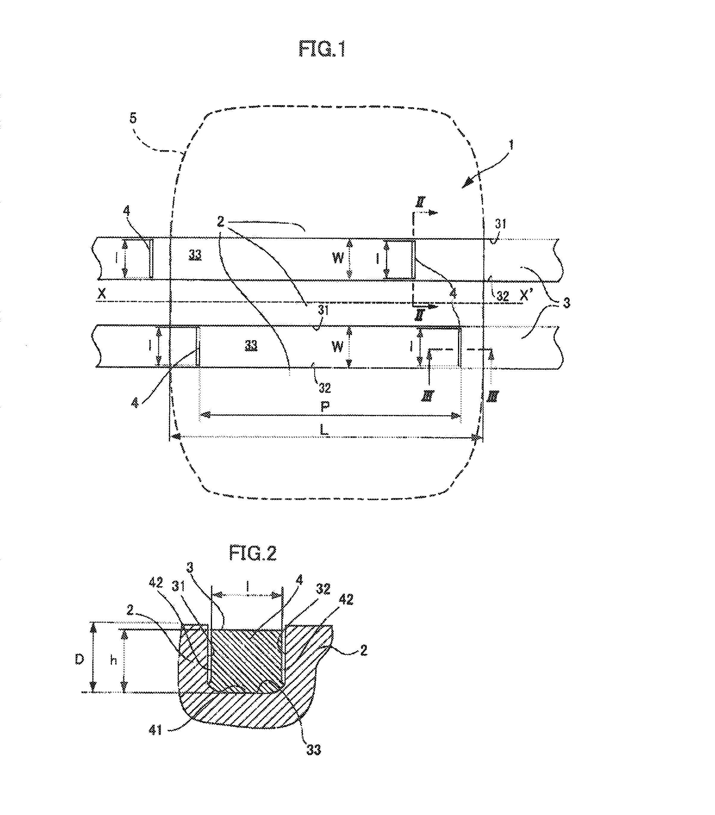
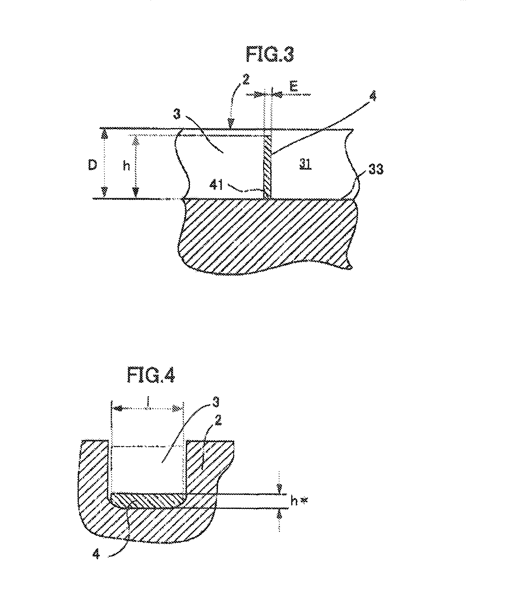
The present patent aims to solve the problem of a flexible fence easily changing shape and causing noise and early abrasion when running on a pneumatic tire. The invention provides a pneumatic tire tread with a primary groove and multiple flexible fences that block at least 70% of the cross-sectional area of the primary groove and are disposed at intervals such that at least one flexible fence is in the primary groove in the tread contact patch when the tire rolls. The flexible fences are formed inside the primary groove and are abraded to a similar extent as the tread portion, reducing air column resonance and noise. The rubber composition for the fences has an abrasion index that is more than or equal to twice the abrasion index of the tread portion and includes a reinforcing filler in an amount less than usual. The technical effect of the invention is to mitigate noise and early abrasion caused by air column resonance and to maintain water drainage performance while preventing the flexible fence from causing noise and early abrasion.

Problems solved by technology

There is therefore a reduction in drainage of water between the pneumatic tire and the road surface and as a result, there is a reduction in operating safety on wet road surfaces.
This difference in the amount of abrasion is a problem in that the flexible fence projects from the surface of the tread portion (the surface of the tread that forms the tread contact patch) and the flexible fence that projects from the tread surface hits the road surface when running and generates noise.
Moreover, there is a problem in that projection of the flexible fence from the tread portion causes unintentional grounding with the road surface and leads to early abrasion and loss of the flexible fence.

Method used


Image

  • Pneumatic tire tread
  • Pneumatic tire tread
  • Pneumatic tire tread

Examples


examples

[0067]In order to clarify the effects of the present invention, a rubber composition according to the present invention was produced by the following steps.

[0068]The rubber composition for the fences and the rubber composition forming the tread portion are produced in an appropriate mixer, preferably using two linked production steps known to a person skilled in the art, that is, a first production step (called the “non-production” step) for thermomechanical working or mixing at a high temperature wherein the maximum temperature is between 110 and 190° C., preferably 130 and 180° C., and a second mechanical working step (“production” step) wherein the temperature is lower, typically lower than 110° C., for instance, between 40 and 100° C. A crosslinking system is introduced to the finishing step (production step).

[0069]The method for producing a rubber composition for fences comprises at least the following processes:

[0070]a process wherein, according to the first (“non-production”)...


PUM


Abstract

A pneumatic tire tread capable of mitigating air column resonance and maintaining drainage performance while ensuring that the flexible fences are abraded to a similar extent to the tread portion is formed from a rubber composition, and has a tread portion in which at least one primary groove is formed and multiple flexible fences is formed in the primary groove; the flexible fences are formed from at least a rubber composition for fences that is different from the rubber composition for the tread portion; the rubber composition for fences of the flexible fences has an abrasion index that is more than or equal to twice the abrasion index of the rubber composition of the tread portion; and the rubber composition for fences comprises a filler composition that is based on (a) a diene elastomer, (b) a reinforcing filler which is less than 50 phr; (c) a plasticizing system, and (d) a vulcanizing system.

Description

[0001]This application claims benefit of the filing date of PCT / JP2011 / 065117, filed Jun. 30, 2011, the entire contents of which is incorporated herein by reference for all purposes.BACKGROUND[0002]1. Field[0003]The present invention relates to a pneumatic tire tread, and in further detail, to a pneumatic tire tread with which flexible fences are formed in the primary groove of the tread and it is thereby possible to reduce air column resonance and maintain water drainage performance while ensuring that the flexible fences and tread portion will be abraded to a similar extent.[0004]2. Description of Related Art[0005]The air column resonance of a primary groove formed in the tread of a tire is generated by resonance inside a tube (air column) formed between the primary groove and the road surface, and this resonance frequency depends on the length of the air column of the primary groove formed with the road surface.[0006]This air column resonance is manifested in the form of noise in...

Claims


Application Information

Patent Timeline
Patent Type & Authority Patents(United States)
IPC IPC(8): B60C11/13B60C1/00B60C11/04
CPCB60C11/1353B60C1/0016B60C11/042B60C2011/1361
Inventor SHIMANAKA, NANAEPAGANO, SALVATOREDAUTREY, NICOLAS
Owner MICHELIN & CO CIE GEN DES ESTAB MICHELIN
Learn More