
Medical intelligent drainage device

An intelligent, driving device technology, applied in the field of medical devices, can solve the problems of increasing the burden on medical staff and patients' families, failing to follow the doctor's expectation, and difficult to guarantee the drainage effect, so as to improve safety and stability, and ensure the drainage effect. , the effect of reducing workload

Inactive Publication Date: 2020-12-04
德州飚丰信息技术有限公司
View PDF0 Cites 4 Cited by
  • Summary
  • Abstract
  • Description
  • Claims
  • Application Information

AI Technical Summary

Problems solved by technology

[0004] In the clinical operation of drainage of a large amount of effusion, there are often specific requirements for clinical parameters such as daily drainage times, each drainage volume, and drainage speed according to the condition of the case. The parameters are usually controlled subjectively by the medical staff or the patient's family members. The current artificial control method has certain disadvantages. As a result, the drainage process cannot be carried out in the way the doctor expected, and the improper drainage will cause discomfort and injury to the patient, and even endanger the patient's life. On the other hand, the real-time drainage volume and drainage speed during the drainage process are usually determined by human observation. Judgment, the error is large, and it is difficult to guarantee the drainage effect. At the same time, the current control method will obviously increase the burden on the medical staff and the patient's family members.

Method used


Image

  • Medical intelligent drainage device
  • Medical intelligent drainage device
  • Medical intelligent drainage device

Examples


Embodiment 1

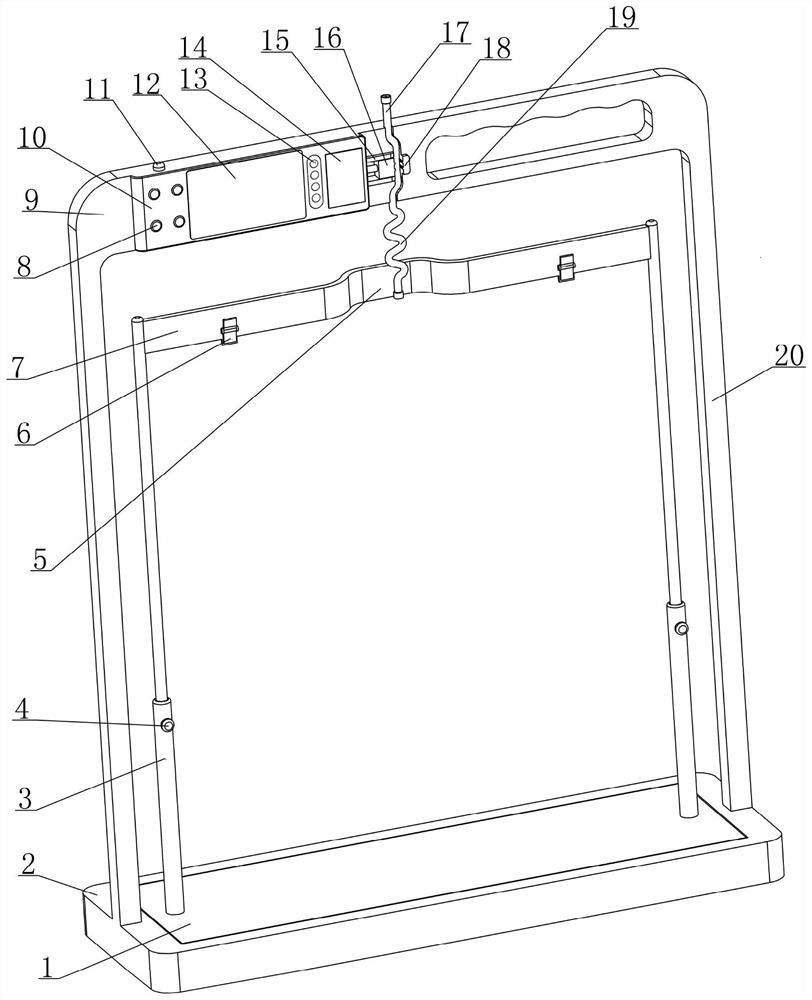
[0032] see Figure 1-7 As shown, a medical intelligent drainage device disclosed in this embodiment is composed of a weighing component, a drainage adjustment assembly, a controller 10 and a power supply component;

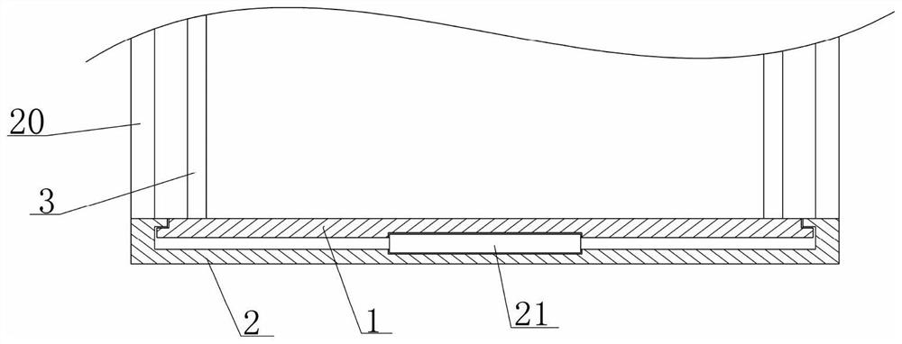
[0033] Among them, see figure 1 , 2, 6, and 7, the weighing assembly includes a weighing mechanism with a weight measurement function formed by matching the weighing platform 1, the load cell 21 and the base 2 up and down in sequence, and the output of the load cell 21 can reflect the The weighing signal of the weight of the object above the weighing platform 1; a suspension arm 7 is supported by two vertical telescopic rods 3 above the weighing platform 1, and at least one telescopic rod 3 is provided with a lock for locking the height of the suspension arm 7 Tight mechanism, the underside of the suspension arm 7 is provided with two fixing clips 6; the suspension arm 7 can use the fixing clips 6 to suspend and fix the drainage bag 24 above the weighing table 1...

Embodiment 2

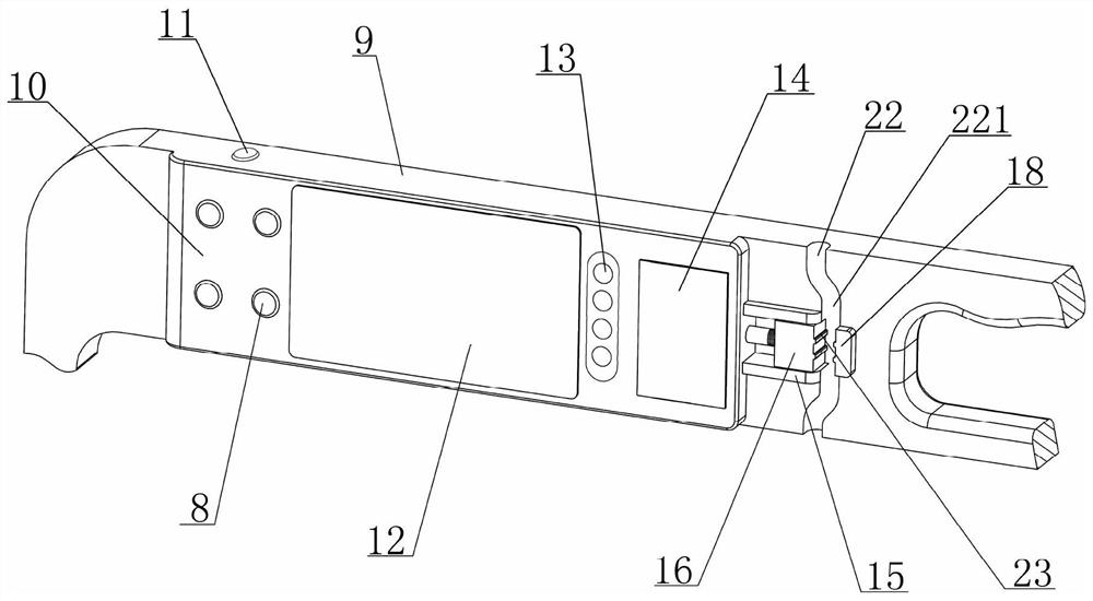
[0051] see image 3 As shown, in the medical intelligent drainage device disclosed in Embodiment 1, the driving device 14 can drive the movable clamp block 16 to move the position based on the control of the controller 10. As far as this technical purpose is concerned, the driving device 14 adopts the prior art to have multiple functions. However, in order to make the structure of the drive device 14 simpler and more compact, this embodiment provides a drive device 14 with a simple structure and stable operation, and its specific implementation structure is as follows:

[0052] see Figure 8 As shown, the driving device 14 includes a motor 141 fixed on the beam 9, the output shaft of the motor 141 is coaxially connected with a screw 142, and the movable clamp 16 is provided with a screw hole 143, and the movable clamp 16 is threaded through the screw. The hole 143 is matched with the lead screw 142 to form a threaded screw mechanism. The motor 141 drives the lead screw 142 to...

Embodiment 3

[0055] see Figure 4 , 5 As shown, in the medical intelligent drainage device disclosed in Embodiment 1, the connecting tube 17 is connected between the drainage bag 24 and the drainage tube 25, and after it is squeezed differently by the adjusting mechanism, the internal section changes accordingly, so that It can realize the adjustment of the on-off state and the flow rate of the internal fluid. Based on this technical purpose, the part of the connecting pipe 17 that cooperates with the adjustment mechanism should have good elastic deformation capacity to ensure that it can quickly occur with the change of the pressure applied by the adjustment mechanism. Deformation, improve the response speed of flow rate adjustment, but if the connecting pipe 17 is made of high-quality elastic material as a whole, it will inevitably increase the cost, and if the part that cooperates with the adjustment mechanism is made of high-quality elastic material, it is not conducive to the processi...


PUM


Abstract

The invention relates to the field of medical apparatus and instruments, and discloses a medical intelligent drainage device. The drainage device consists of a weighing assembly, a drainage adjustingassembly, a controller and a power supply assembly; the weighing assembly is used for feeding back weighing signals capable of reflecting the change of an effusion in a drainage bag to the controller;the drainage adjusting assembly consists of a gantry, a connecting tube and an adjusting mechanism; the connecting tube is used for connecting the drainage bag and a drainage tube; the adjusting mechanism is driven by a driving device to extrude the connecting tube to different extents so as to achieve the purpose of adjusting the flow rate of the effusion in the connecting tube; and the controller can control the adjusting mechanism based on the weighing signals obtained during drainage and preset drainage parameters, so that automatic drainage can be realized. Through intelligent design, the drainage device can realize the automatic control of timed drainage, quantitative drainage and constant speed drainage by cooperative using with existing conventional drainage assemblies; and therefore, the safety and stability of drainage operation can be enhanced, manpower can be saved, drainage effects can be guaranteed, and the drainage device is convenient and efficient in using.

Description

[0001] The present invention is a divisional application of the invention patent application with application number 2018111350276 submitted on September 28, 2018. technical field [0002] The invention relates to the technical field of medical devices, in particular to an intelligent drainage device that can be used in clinical drainage operations. Background technique [0003] Drainage is a commonly used clinical treatment, such as peritoneal effusion, pleural effusion and other diseases need to use drainage for treatment. Taking pleural effusion as an example, there are 3ml to 15ml of fluid in the pleural cavity of normal people, which acts as a lubricant during respiratory movement. These fluids are continuously formed and absorbed to maintain a dynamic balance. If this balance is destroyed by disease, resulting in If the liquid in the pleural cavity is formed too fast or absorbed too slowly, pleural effusion will be formed, which is also called pleural effusion in clini...

Claims


Application Information

Patent Timeline
Patent Type & Authority Applications(China)
IPC IPC(8): A61M1/00
CPCA61M2205/3334A61M2205/3393
Inventor 王才丰
Owner 德州飚丰信息技术有限公司
Learn More