
Chest compression system and method

a compression system and chest compression technology, applied in the field of chest compression, can solve the problems of insufficient depth calculation and insufficient accuracy, and achieve the effect of improving the system accuracy

Active Publication Date: 2020-06-23
ZOLL CIRCULATION
View PDF6 Cites 1 Cited by
  • Summary
  • Abstract
  • Description
  • Claims
  • Application Information

AI Technical Summary

Benefits of technology

[0006]Assuming that the x, y and z axes of the accelerometers are parallel (not necessarily aligned, just parallel), a depth calculation is accurate and provides a basis for useful feedback to a CPR provider or CPR chest compression device. If the x, y and z axes of the accelerometers are not parallel, and are substantially non-parallel, the depth calculation may not be as accurate as desired. To improve the accuracy of the system, the control system described below is programmed to determine the relative orientation of the first and second accelerometer assemblies, and then rotate or project one or more the x, y and z movement vectors as determined from the first accelerometer assembly into the x, y and z frame of the second accelerometer assembly, and thereafter combining the rotated vectors of the first accelerometer with the vectors of the second accelerometer to determine the chest compression depth achieved by CPR compressions. (As an initial step, the relative orientation of the accelerometers is determined by sensing the acceleration of gravity, as sensed by both accelerometers, to establish a rotation matrix to be applied to the measured movement vectors before combination.)

Problems solved by technology

If the x, y and z axes of the accelerometers are not parallel, and are substantially non-parallel, the depth calculation may not be as accurate as desired.

Method used


Image

  • Chest compression system and method
  • Chest compression system and method
  • Chest compression system and method

Examples


Embodiment Construction

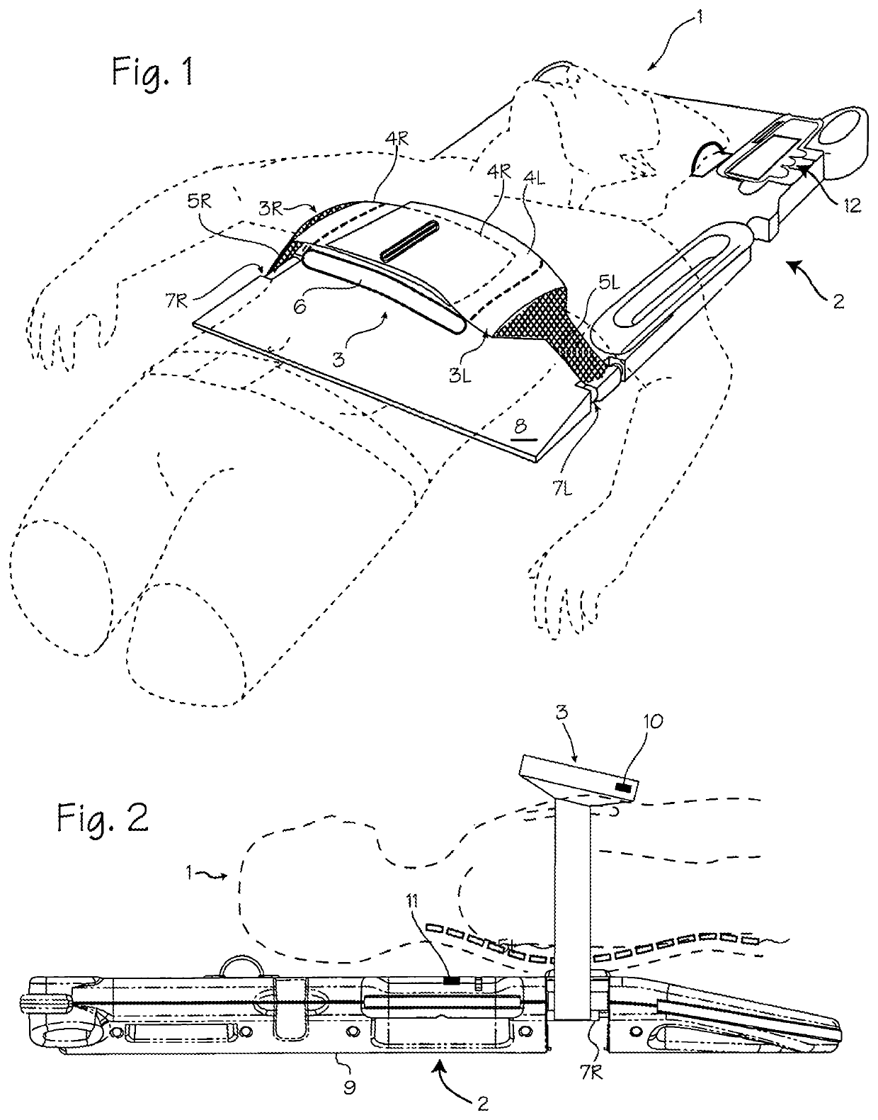
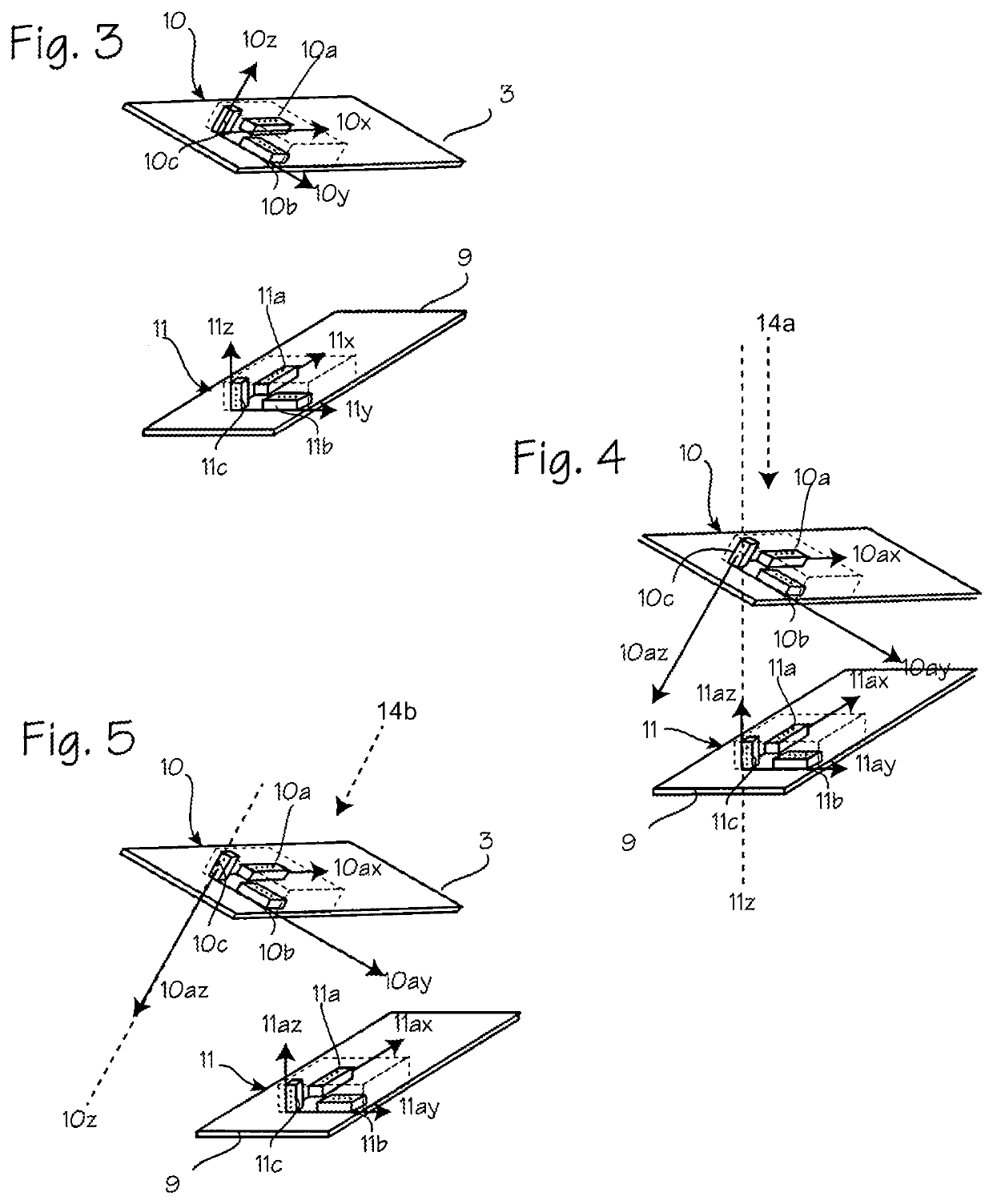
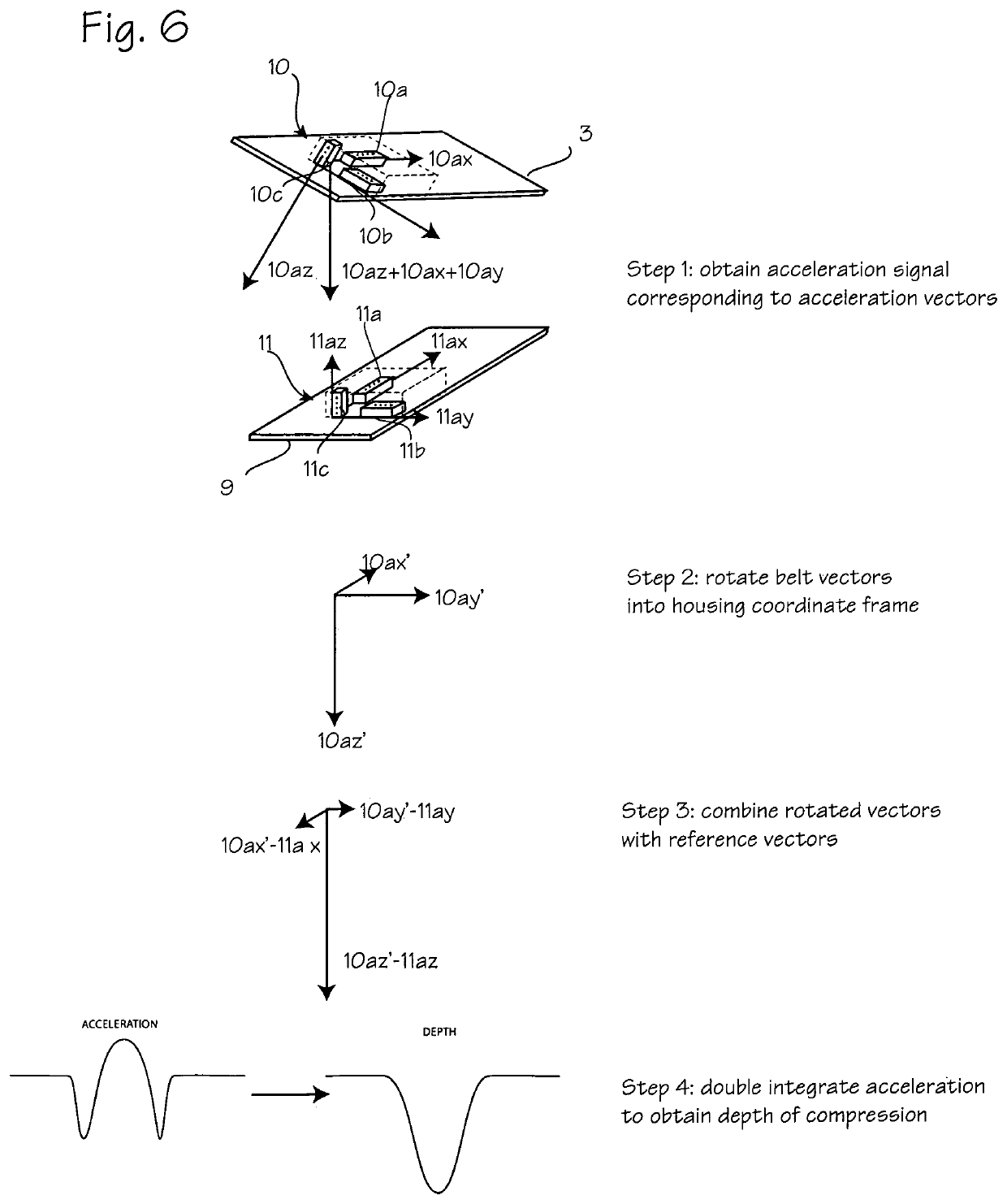
[0014]Though the compression monitor system described in this application can be used to provide feedback for manual CPR and automated CPR using a variety of different chest compression devices, it is described here in the context of providing feedback for a belt driven chest compression device. FIGS. 1 and 2 illustrate a belt-driven chest compression system fitted on a patient 1. The belt-driven chest compression device 2 applies compressions with the belt 3 (which may comprise right belt portion 3R and a left belt portion 3L) and load distributing portion 4 (which may comprise a single piece belt, or may comprise right and left load distributing portions 4R and 4L) designed for placement over the anterior surface of the patient's chest while in use, and tensioning portions which extend from the load distributing portions to a drive spool, shown in the illustration as narrow pull straps 5R and 5L. A bladder 6 may be disposed between the belt and the chest of the patient. The narrow...


PUM


Abstract

A system and method for determining CPR induced chest compression depth using two sensors while accounting for different orientations of the two sensors. The system may include a first motion sensor operable to generate motion signals corresponding to motion in a first coordinate frame defined by a first set of axes and a second motion sensor operable to generate motion signals corresponding to motion in a second coordinate frame defined by a second set of axes and a control system operable to receive the motion signals from the first motion sensor and the second motion sensor, rotate the motion signals from the first motion sensor into the second coordinate frame to obtain rotated motion signals corresponding to the motion signals from the first motion sensor, and combine the rotated motion signals with the motion signals from the second motion sensor to generate an output indicative of said displacement.

Description

FIELD OF THE INVENTIONS[0001]The inventions described below relate to the field of CPR.BACKGROUND OF THE INVENTIONS[0002]Halperin, et al., CPR Chest Compression Monitor, U.S. Pat. No. 6,390,996 (May 21, 2002) discloses a CPR chest compression monitor which uses a compression sensor, e.g. an accelerometer, to measure acceleration of a patient's chest wall due to CPR compressions to calculates the depth of compressions based on acceleration signals provided by the accelerometer.[0003]Palazzolo, et al., Method of Determining Depth of Chest Compressions During CPR, U.S. Pat. No. 7,122,014 (Oct. 17, 2006) discloses the use of a chest compression monitor with a chest compression device, such as the AutoPulse® chest compression device, with an accelerometer in the belt, and an accelerometer fixed to the supporting surface is used as a reference sensor.[0004]Halperin disclosed a compression monitor, e.g. comprising an accelerometer and a control system for processing accelerometer signals t...

Claims


Application Information

Patent Timeline
Patent Type & Authority Patents(United States)
IPC IPC(8): A61H31/00A61H11/00
CPCA61H31/008A61H31/004A61H31/007A61H2201/501A61H2201/5061A61H2201/1623A61H2201/5064A61H2011/005A61H2201/5084A61H2201/1604A61H2230/06A61H31/005A61H31/006A61H2201/5058A61H2201/50A61H2205/084
Inventor JOSHI, NIKHIL S.GEHEB, FREDERICK J.CAMPANA, LISA M.
Owner ZOLL CIRCULATION
Learn More