Method of distributing air ventilation in a vehicle

a technology of air ventilation and vehicle, which is applied in the direction of vehicle cleaning, domestic cooling apparatus, defrosting, etc., can solve the problems of increasing the cost and complexity of manufacturing the air handling system, and undesirable nvh, so as to achieve efficient and cost-saving effects

Active Publication Date: 2020-06-23
HANON SYST
View PDF10 Cites 0 Cited by
  • Summary
  • Abstract
  • Description
  • Claims
  • Application Information

AI Technical Summary

Benefits of technology

[0013]Concordant and consistent with the present invention, an efficient and lost cost method of controlling a flow of air to windshield defrost vents and side window defrost vents of a passenger compartment by adjusting a position of a control door has surprisingly been discovered.

Problems solved by technology

One problem associated with the distributing of the air to each of the vents of the delivery section is related to differences in a volumetric flow rate and pressure of the air required at the outlet of each of the vents to achieve the desired distribution of the air for each of the operating modes.
The problem associated with the control of the flow of the air through each independent flow path is especially evident when attempting to control the pressure of the air associated with the outlets of the windshield defrost vents and the outlets of the side window defrost vents.
Accordingly, the variation in pressure required in each of the respective passageways frustrates an attempt to simultaneously control the pressure within each passageway by actuating the door disposed upstream of the defrost chamber, as an attempt to control the pressure in one of the flow paths will also affect the ability to control the pressure in the other of the flow paths.
This problem is further evident in view of changing demands in the distribution of the air to the various vents of the passenger compartment based on the corresponding operating mode, and especially changing demands to the percentage of the air delivered to the side window defrost vents during the floor operating mode, the defrost operating mode, and a mixed floor / defrost operating mode.
However, this solution may require the addition of multiple components such as doors, actuators, links, or control elements, thereby increasing a cost and complexity to manufacture the air handling system.
The variation in the distribution of the air for the various different operating modes to the windshield defrost vents and the side window defrost vents also poses additional problems relating to the noise, vibration, and harshness (NVH) generated by the flow of the air while flowing through the delivery section.
These conditions may result in a situation where the air delivered to either of the windshield defrost vents or the side window defrost vents must travel through a relatively small gap while passing from a high pressure chamber (the mixing section) to a relatively low pressure chamber (either of the windshield defrost pathway or the side window defrost pathway), thereby resulting in a rapid expansion of the air in a manner that may cause undesirable NVH.

Method used


Image

  • Method of distributing air ventilation in a vehicle
  • Method of distributing air ventilation in a vehicle
  • Method of distributing air ventilation in a vehicle

Examples


Embodiment Construction

[0031]The following detailed description and appended drawings describe and illustrate various embodiments of the invention. The description and drawings serve to enable one skilled in the art to make and use the invention, and are not intended to limit the scope of the invention in any manner. In respect of the methods disclosed, the steps presented are exemplary in nature, and thus, the order of the steps is not necessary or critical.

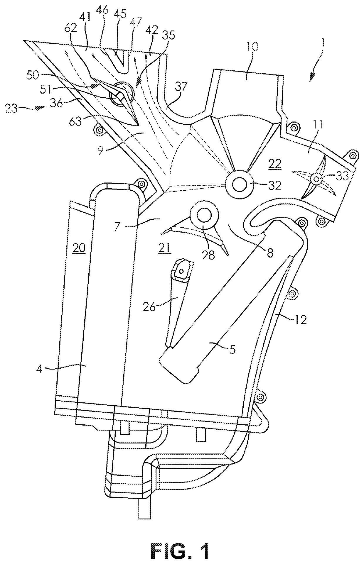
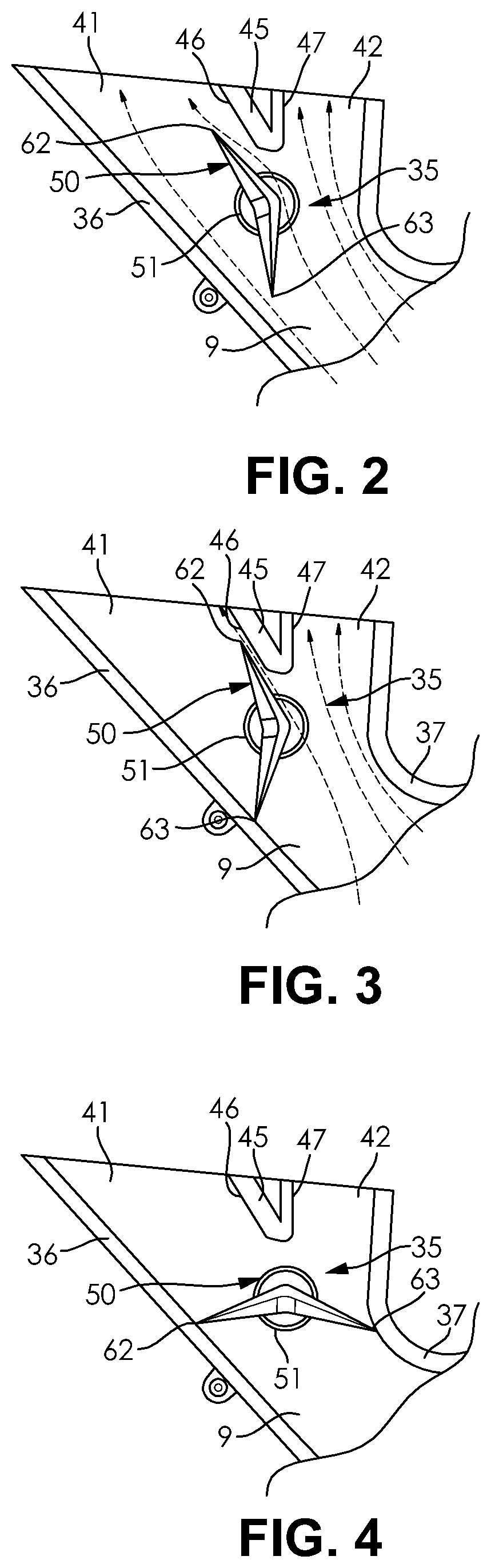
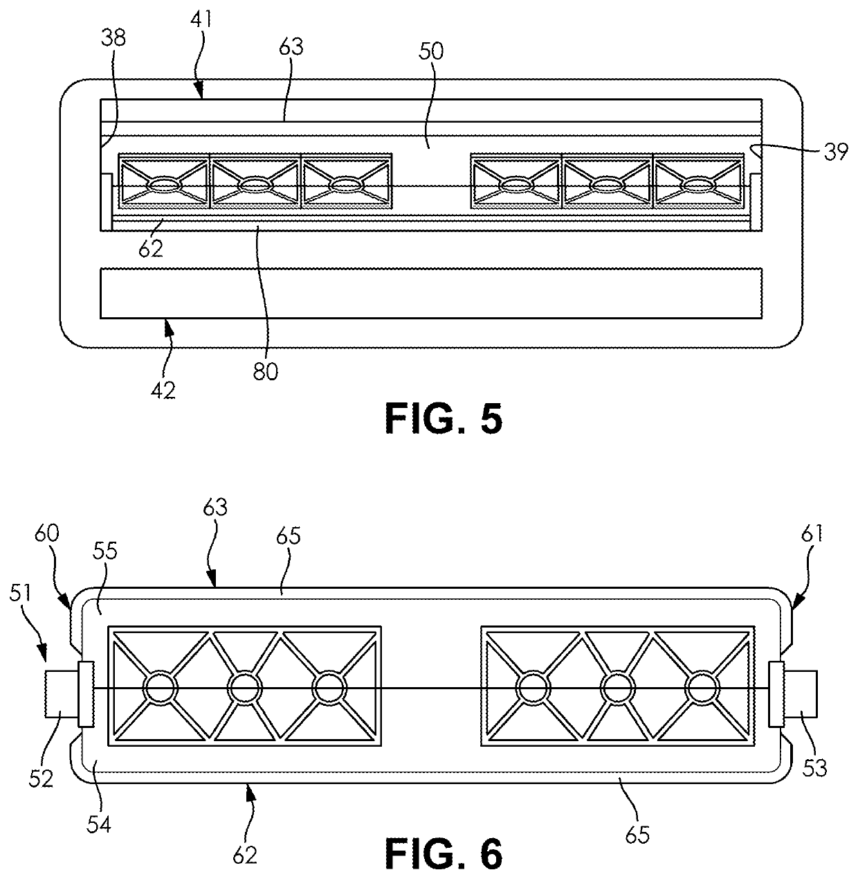
[0032]FIGS. 1-6 illustrate an air-handling system 1 of a heating, ventilating, and air conditioning (HVAC) system for a vehicle (not shown) according to an embodiment of the invention. As used herein, the term air can refer to fluid in a gaseous state, fluid in a liquid state, or any combination thereof. The air-handling system 1 typically provides heating, ventilation, and air conditioning for a passenger compartment (not shown) of the vehicle.

[0033]The air-handling system 1 includes a hollow main housing 12. The main housing 12 may be formed by the ...


PUM


Abstract

An air-handling system for a heating, ventilation, and air conditioning system of a vehicle includes a main housing comprising a conditioning section, a mixing section, and a delivery section having a flow of air passing therethrough. The delivery section includes a conduit branching into a windshield defrost pathway and a demist pathway, the windshield defrost pathway leading to windshield defrost vents of a passenger compartment of the vehicle and the demist pathway leading to side window defrost vents of the passenger compartment. A control door rotatably disposed in the conduit is adjustable through a range of rotational positions wherein a flow area through the windshield defrost pathway is variably restricted while the demist pathway remains unobstructed. The control door is further adjustable to a position wherein the windshield defrost pathway and the demist pathway are closed.

Description

FIELD OF THE INVENTION[0001]The invention relates to a climate control system for a vehicle, and more particularly to a climate control system for a heating, ventilating, and air conditioning system for the vehicle.BACKGROUND OF THE INVENTION[0002]A vehicle typically includes a climate control system which maintains a temperature within a passenger compartment of the vehicle at a comfortable level by providing heating, cooling, and ventilation. Comfort is maintained in the passenger compartment by an integrated mechanism referred to in the art as a heating, ventilation and air conditioning (HVAC) air-handling system. The air-handling system conditions air flowing therethrough and distributes the conditioned air throughout the passenger compartment.[0003]The air-handling system commonly employs a housing having a plurality of passageways and doors for controlling a temperature and a flow of the air therethrough. The housing may for example be divided into an inlet section, a conditio...

Claims


Application Information

Patent Timeline
Patent Type & Authority Patents(United States)
IPC IPC(8): B60S1/54B60S1/58B60H1/00F25D21/12
CPCB60H1/00678F25D21/125B60S1/54B60H1/00835B60H1/00028B60H2001/00092B60H2001/007
Inventor IYER, JAYANTHI R.HAUPT, ERICVERMETTE, DENNISNOLTA, JIMPATIL, SHANKARCONLEY, MARK DOUGLAS
Owner HANON SYST
Why Eureka
Try Eureka