Input control method of touch panel monitor for working machine

a touch panel monitor and working machine technology, applied in the direction of machine control, electric controllers, instruments, etc., can solve the problems of unplanned operation, unintentional operation of operators, and possible changes in display, so as to prevent unintended input operation of operators, prevent the possibility of operators, and prevent the effect of inpu

Active Publication Date: 2020-06-23
CATEPILLAR SARL
View PDF21 Cites 0 Cited by
  • Summary
  • Abstract
  • Description
  • Claims
  • Application Information

AI Technical Summary

Benefits of technology

[0017]With the foregoing in view, an object of the present invention is to provide an input control method of a touch panel monitor for a working machine capable of preventing an unintended operation input on a touch panel while enabling monitor screen display.
[0022]According to the invention of claim 1, in the touch panel monitor mounted on the working machine, when the working machine is operable, the monitor input lock state where necessary information is obtained from the monitor screen display and the monitor input operation on the touch panel is disabled is created. When the monitor input lock state is released, a specific monitor input unlock operation on the touch panel is required. Thus, even when the operator during operating the working machine performs an unintended operation to touch on the touch panel, it is possible to prevent the input of an unintended operation on the touch panel.
[0023]According to the invention of claim 2, control is performed such that the touch panel enters into the monitor input lock state when the hydraulic lock state is switched to the hydraulic unlock state by the hydraulic lock switch. Thus, when the working machine enters into an operable state in accordance with the switching from the hydraulic lock state to the hydraulic unlock state, the monitor input operation from the touch panel is automatically disabled. Therefore, it is possible to reliably prevent the input of an unintended operation on the monitor simultaneously with the working machine entering into the operable state.
[0024]According to the invention of claim 3, control is performed such that the touch panel automatically enters into the monitor input lock state when there is no monitor input operation on the touch panel for a predetermined period even in a state where the monitor input operation is enabled. Thus, it is possible to prevent an unintended input operation of the operator by urging the operator to perform a monitor input unlock operation and a monitor input operation on the touch panel.
[0025]According to the invention of claim 4, when an operation screen that influences the operation of the working machine is displayed on the touch panel, control is performed such that a setting change screen is displayed by simultaneously touching a plurality of positions on the touch panel, which is difficult to perform unintentionally. Thus, it is possible to reduce the possibility of the operator performing an unintended monitor input operation.

Problems solved by technology

Thus, when an operator of a working machine touches on a touch panel unintentionally, an unexpected operation (that is, an operation that is not intended by an operator) may occur.
Due to this, troubles such as an operation that is not intended by an operator or a change in display are likely to occur as compared to a monitor having a select switch.
Thus, the possibility of the operator touching on the touch panel unintentionally is high as compared to an automobile or the like, for example.
In this case, the touch panel may mistake the touch for a monitor input operation and the possibility of the occurrence of an operation that is not intended by the operator increases.
When a touch panel monitor is employed and such a setting screen is displayed and operated unintentionally, the working machine may perform an operation that is not intended by the operator.

Method used


Image

  • Input control method of touch panel monitor for working machine
  • Input control method of touch panel monitor for working machine
  • Input control method of touch panel monitor for working machine

Examples


Embodiment Construction

[0031]Hereinafter, the present invention will be described in detail based on an embodiment illustrated in FIGS. 1 to 5.

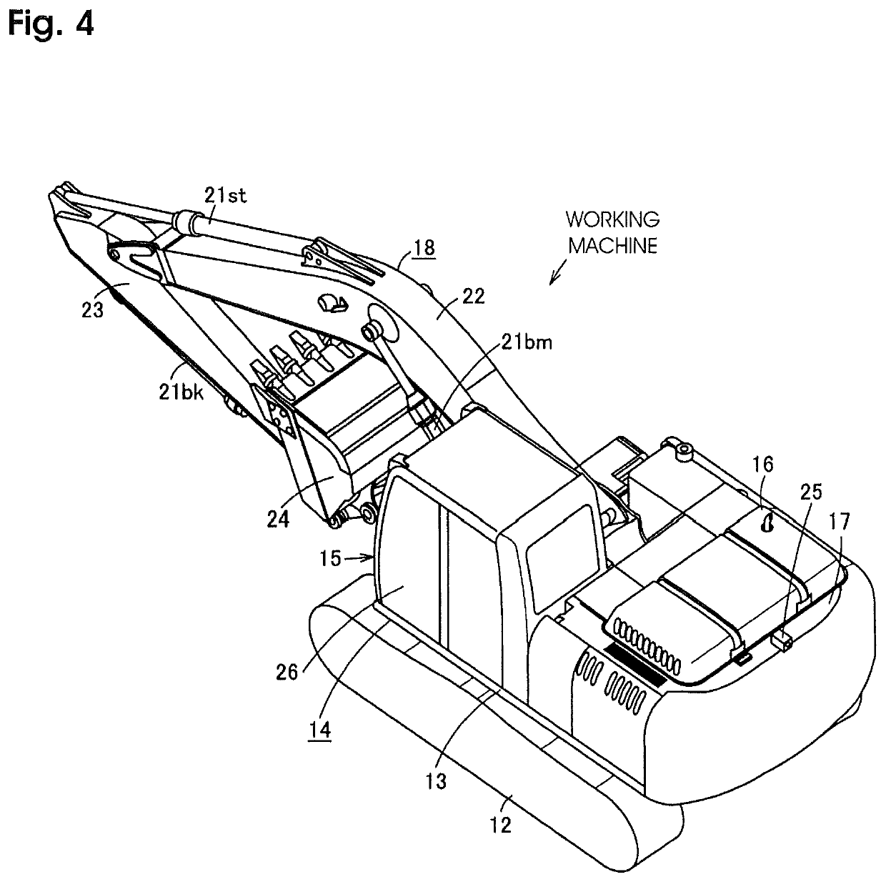
[0032]FIG. 4 illustrates a working machine (excavator) 11, and the working machine 11 includes a body 14 which includes a lower traveling body 12 and an upper swinging body 13 that is swingably provided on the lower traveling body 12.

[0033]A working unit 18 that operates with operating hydraulic pressure is provided on the upper swinging body 13 together with a cab 15, a power unit 16, a counterweight 17, and the like. The working unit 18 includes a boom 22, a stick 23, a bucket 24, and the like which are pivoted by hydraulic actuators such as a boom cylinder 21bm, a stick cylinder 21st, a bucket cylinder 21bk, and the like. A rear-view monitor camera 25 that captures a rear-view image of the base 14 is provided in a central portion of the upper surface of the counterweight 17.

[0034]A hatch 26 through which an operator enters and exits the cab 15 is provided on the...


PUM


Abstract

Method for controlling input to a touch panel includes a monitor screen display displaying a rear camera image screen, a measurement screen at the touch panel, and an input operation screen display in which an input operation can be performed. When the machine is operable, a monitor screen can be displayed in an input lock state in which the input operation is inhibited by turning off a hydraulic lock switch and releasing a hydraulic lock state. A specific input lock releasing operation on the touch panel releases the lock and the monitor screen display is switched to the input operation screen display.

Description

CROSS-REFERENCE TO RELATED APPLICATIONS[0001]This application is a national phase application of International Patent Application N. PCT / EP2015 / 058144, filed Apr. 15, 2015, which claims priority to Japanese Patent Application No. JP 2014-084681, filed Apr. 16, 2014, both of which are incorporated by reference herein in their entireties for all purposes.TECHNICAL FIELD[0002]The present invention relates to an input control method of a touch panel monitor for a working machine having an input function.BACKGROUND ART[0003]A monitor capable of assisting in operating a working machine such as an excavator and allowing an operator to perform maintenance of the working machine is mounted beside of a driver's seat of the working machine, and in many cases, the monitor is disposed in a deep front side of a cab (the right front side seen from the operator) (for example, see Patent Literatures 1 and 2).[0004]In such a monitor, a rear-view camera image obtained with a rear-view monitor camera o...

Claims


Application Information

Patent Timeline
Patent Type & Authority Patents(United States)
IPC IPC(8): E02F9/16E02F9/26E02F3/32F15B15/26B60K37/06F15B21/08B60K35/00E02F9/22E02F9/20B60K31/00
CPCE02F9/26B60K31/00F15B21/08E02F9/226F15B15/26B60K37/06E02F9/2292E02F9/16E02F9/2004B60K35/00E02F9/2296B60K2370/145F15B2211/6303B60K2370/61B60K2370/1438E02F3/32B60R16/02G05B11/01G06F3/041
Inventor YAMADA, HIDEO
Owner CATEPILLAR SARL
Why Eureka
Try Eureka