
Coil component

a coil and component technology, applied in the direction of coils, transformer/inductance details, electrical devices, etc., can solve the problems of difficult automation of assembly using robots, difficult complex assembly process, etc., to improve assembly efficiency, simplify assembly process, and reliably catch chips and burrs

Active Publication Date: 2020-06-23
TDK CORPARATION
View PDF17 Cites 0 Cited by
  • Summary
  • Abstract
  • Description
  • Claims
  • Application Information

AI Technical Summary

Benefits of technology

[0004]The present invention was conceived in view of the problem described above and has a principal object of providing a coil component capable of improving assembly efficiency and preventing electrical shorting.
[0013]With the above coil component according to the present invention, by providing the first bobbin member with the first positioner that positions the first coil member when the first coil member is moved along a center axis of the barrel from the front end of the barrel toward the base plate and the second positioner that positions the second coil member when the second coil member is moved along the center axis from the front end of the barrel toward the base plate, it is possible to position the respective coil members with respect to the first bobbin member by merely moving the coil members in a single direction (i.e., from the front end of the barrel toward the base plate). This means that according to the above coil component, compared to a conventional configuration that inserts the barrel of the coil bobbin into the two coil windings from different directions and positions the coil bobbin and the respective coil windings by rotating the coil windings with respect to the coil bobbin, it is possible to sufficiently simplify the assembly process. Since the assembly process is simplified, it is possible to automate the assembly using a robot, and as a result, it is possible to sufficiently improve the assembly efficiency. Also, according to the above coil component, by equipping the first bobbin member with the support that is formed so as to be capable of surrounding and supporting lower portions of the respective joints of the coil members, even if chips and burrs are produced by screwing a screw into the first joining hole when joining the first joint of the first coil member and the second joint of the second coil member, it is possible to reliably catch the chips and burrs using the support. This means that according to the above coil component, it is possible to reliably avoid a situation where chips and burrs fall onto electric circuits or the like on which the coil component is incorporated and cause electrical shorting.

Problems solved by technology

More specifically, when assembling the coil component described above, it is necessary to insert one end of the barrel of the coil bobbin into the opening in the first coil winding and to insert the other end of the barrel of the coil bobbin into the opening in the second coil winding (that is, to insert the barrel of the coil bobbin from different directions into the respective openings of the coil windings) and to rotate the coil windings with respect to the coil bobbin to fix the coil bobbin and the coil windings in the positioned state, which makes the assembly process complex.
Further, since the assembly process (in particular, the step of rotating the coil windings) is complex, it is difficult to automate assembly using robots and therefore difficult to improve the assembly efficiency.
With this configuration, when the screw is tightened, the terminals may become shaved by the screw to produce chips or burrs, and when these chips or burrs fall off onto a circuit board or the like on which the coil component has been incorporated, this can cause electrical shorting.

Method used


Image

  • Coil component
  • Coil component
  • Coil component

Examples


Embodiment Construction

[0035]Preferred embodiments of a coil component will now be described with reference to the attached drawings.

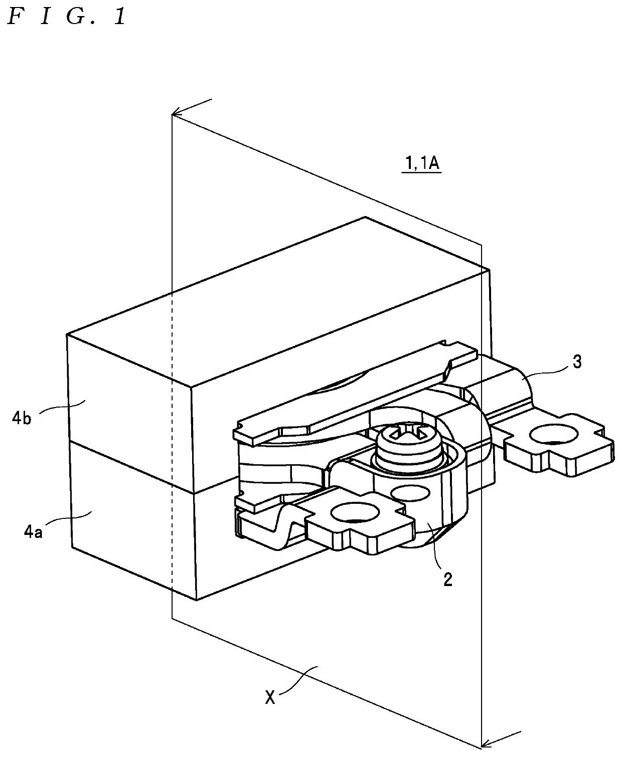
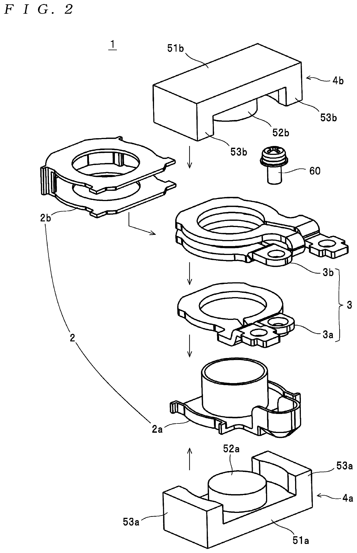
[0036]First, the configuration of a coil component 1 depicted in FIG. 1 will be described as an example of a coil component. The coil component 1 is an electrical component to be used in a switching power supply, for example, and as depicted in FIG. 1 and FIG. 2, includes a bobbin 2, a coil 3, and cores 4a and 4b. Note that a component composed of the bobbin 2 and the coil 3 without the cores 4a and 4b is also included in the intended meaning of the expression “coil component” used here.

[0037]As depicted in FIG. 2, the bobbin 2 includes a first bobbin member 2a (one example of a “first bobbin member” for the present invention) and a second bobbin member 2b (one example of a “second bobbin member” for the present invention).

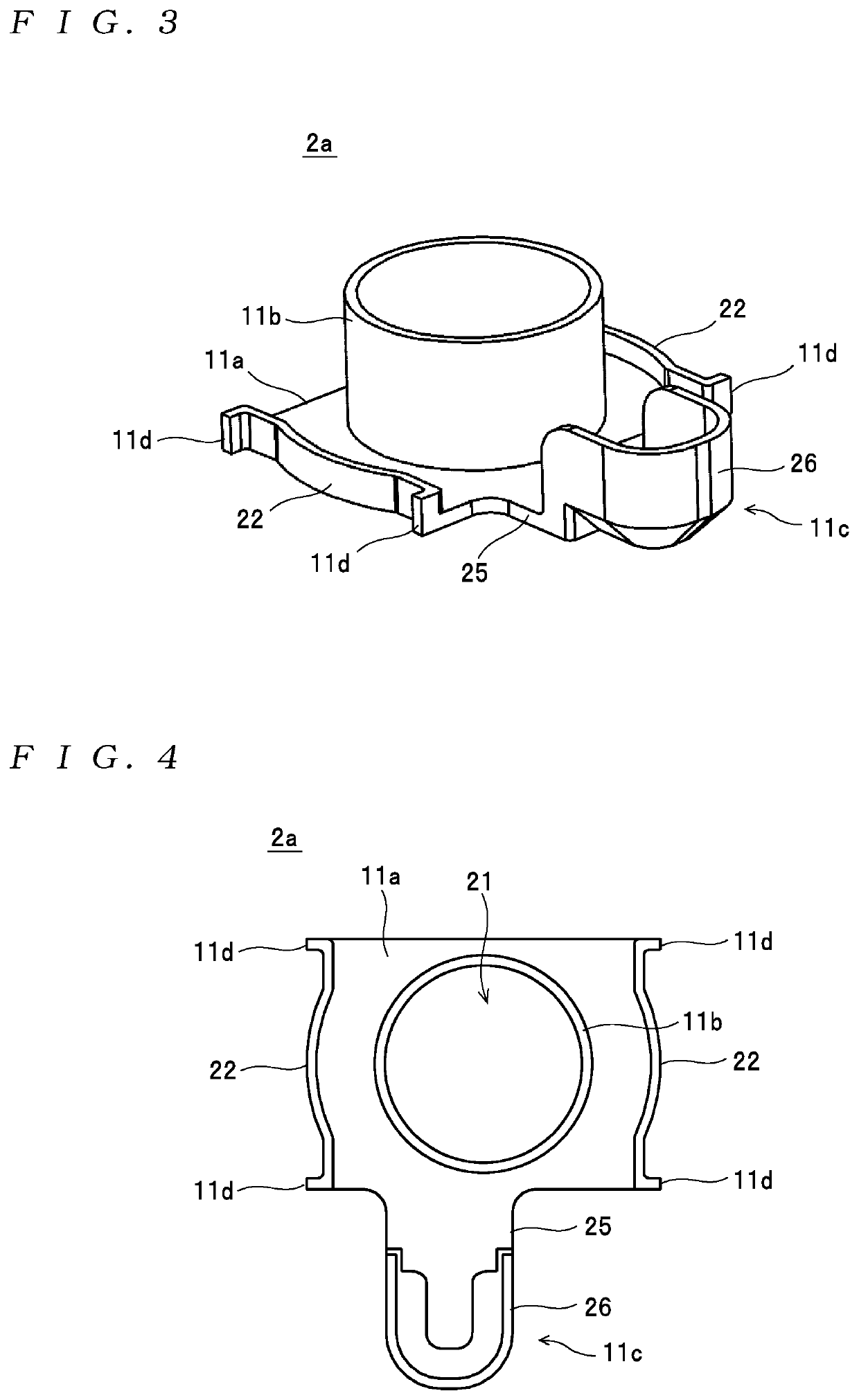
[0038]As depicted in FIGS. 3 and 4, the first bobbin member 2a includes a base plate 11a, a barrel 11b, a support 11c, and four projecting portions 11d, w...


PUM

PropertyMeasurementUnit
distanceaaaaaaaaaa
timeaaaaaaaaaa
electricallyaaaaaaaaaa

Abstract

A coil component includes a non-conductive bobbin and a coil that winds around the bobbin. The coil includes first and second coil members with joining portions in which joining holes are formed. The bobbin includes first and second bobbin members. The first bobbin member includes: first and second positioning portions that position the first and second coil members, respectively, when the first and second coil members are moved onto the first bobbin member; and a support that supports lower portions of the first and second joining portions. The second bobbin member includes a first insulator disposed between the first and second coil members. The first and second coil members and the second bobbin member are attached to the first bobbin member by being moved in a single direction without a further step of rotating.

Description

FIELD OF THE INVENTION[0001]The present invention relates to a coil component equipped with a bobbin and a coil that winds around the bobbin.DESCRIPTION OF THE RELATED ART[0002]A coil component disclosed by the present applicant in Patent Literature 1 (Japanese Patent No. 5,273,192 (See Pages 4 to 9, and FIGS. 7, 8, and 10)) is known as one example of this type of coil component. This coil component includes a coil bobbin, a first coil winding, a second coil winding, and a screw as a connection member. When the coil component is assembled, the rear surface of the first coil winding and one end of the coil bobbin are placed facing one another and then projecting portions provided on the same end of the coil bobbin and notches provided in the first coil winding are aligned. After this, one end of a barrel of the coil bobbin is inserted into an opening provided in the first coil winding. At this time, the projecting portions of the coil bobbin are inserted through the notches of the fi...

Claims


Application Information

Patent Timeline
Patent Type & Authority Patents(United States)
IPC IPC(8): H01F27/32H01F27/30H01F27/28H01F5/02
CPCH01F27/325H01F27/306H01F27/2847H01F27/303H01F2027/2861H01F5/02H01F5/06H01F2005/025
Inventor KAN, MASAKIWU, HAN
Owner TDK CORPARATION
Learn More