
Method to verify identity using a previously collected biometric image/data

a biometric image and fingerprint technology, applied in the field of facial recognition authentication systems, can solve the problems of user decision to deactivate such cumbersome security measures, cumbersome password typing, and high cost of fingerprint systems for use on small electronic devices, and achieve the effect of enhancing the security of the system

Active Publication Date: 2020-06-30
FACETEC INC
View PDF264 Cites 10 Cited by
  • Summary
  • Abstract
  • Description
  • Claims
  • Application Information

AI Technical Summary

Benefits of technology

[0010]The authentication system may include feedback displayed on the mobile device to aid a user in learning and authentication with the system. For instance, an accuracy meter may provide feedback on a match rate of the authentication biometrics or movement. A movement meter may provide feedback on the movement detected by the mobile device.
[0013]The system may also provide gradual access to user account(s) when the user first sets up the authentication system. As the user successfully implements the system, authorization may be expanded. For example, during a time period as the user gets accustomed to the authentication system, lower transaction limits may be applied.
[0015]To facilitate imaging in low-light, portions of the screen other than the video feedback may be displayed in a bright color, such as white. In some embodiments, and LED or infrared light may be used, and near infrared thermal imaging may be done with an infrared camera. The mobile device used for imaging may thus have multiple cameras for capture visible light and infrared images. The mobile device may also have multiple cameras (two or more) imaging in a single spectrum or multiple spectrum to provide stereoscopic, three-dimensional images. In such an embodiment, the close-up frames (zoomed) may create the most differentiation as compared to images captured from a distance. In such an embodiment, the frames captured at a distance may be unnecessary.
[0017]In some embodiments, the system may provide prompts on a video feedback display to aid the user in moving the device relative to the user's head during enrollment and / or authentication. The prompts may include ovals or frames displayed on the display screen in which the user must place his or her face by moving the mobile device until his or her face is within the oval or frame. The prompts may preferably be of differing sizes and may also be centered on different positions of the screen. When an actual, three-dimensional person images himself or herself close up and far away, it has been found that the biometric results are different due to the barrel distortion effect of the lens at the different distances. Thus, a three-dimensional person may be validated when biometric results are different in the close-up and far away images. This also allows the user to have multiple biometric profiles for each of the distances.
[0018]In other embodiments, biometrics from images obtained between the close-up and far away images may be analyzed for incrementally different biometric results. In this manner, the morphing of the face from the far face to the warped close up face is captured and tracked. The incremental frames during an authentication may then be matched to frames captured at similar locations during enrollment along the motion path and compared to ensure that the expected similarities and difference are found. This results in a motion path and captured image and biometric data that can prove a three-dimensional person is presently being imaged. Thus, not only are the close-up and far away biometrics compared, but also biometric data obtained in between. The biometric data obtained in between must also correspond to a correct morphing speed along the motion path, greatly enhancing the security of the system.
[0021]In some embodiments, the match thresholds required may be adapted over time. The system may thus account for changing biometrics due to age, weight gain / loss, environment, user experience, security level, or other factors. In further embodiments, the system may utilize image distortion prior to obtaining biometric information to further protect against fraudulent access.

Problems solved by technology

With smaller electronic devices, such as smart phones, smart watches, “Internet of Things” (“IoT’) devices and the like, it may become cumbersome to attempt to type such long passwords into the device each time access to the account is desired and if another individual learns the user's password then the user can be impersonated without actually being present themselves.
In some instances, users may even decide to deactivate such cumbersome security measures due to their inconvenience on their devices.
However, such fingerprint systems are often prohibitively expensive for use on a small electronic device, or are often considered unreliable and unsecure.
Facial recognition software, however, has not been widely implemented on its own to securely authenticate users attempting to gain access to an account because it not considered secure enough.
For example, two-dimensional facial recognition is considered unsecure because faces may be photographed or recorded, and then the resulting prints or video displays showing images of the user may be used to trick the system.
When an actual, three-dimensional person images himself or herself close up and far away, it has been found that the biometric results are different due to the barrel distortion effect of the lens at the different distances.
When authentication fails, the system may be configured so that it is unclear which security layer triggered the failure to preserve the integrity of the security system.

Method used


Image

  • Method to verify identity using a previously collected biometric image/data
  • Method to verify identity using a previously collected biometric image/data
  • Method to verify identity using a previously collected biometric image/data

Examples


Embodiment Construction

[0066]A system and method for providing secure and convenient facial recognition authentication will be described below. The system and method may be achieved without the need for additional expensive biometric readers or systems while offering enhanced security over conventional facial recognition systems.

Facial Recognition Authentication Environment

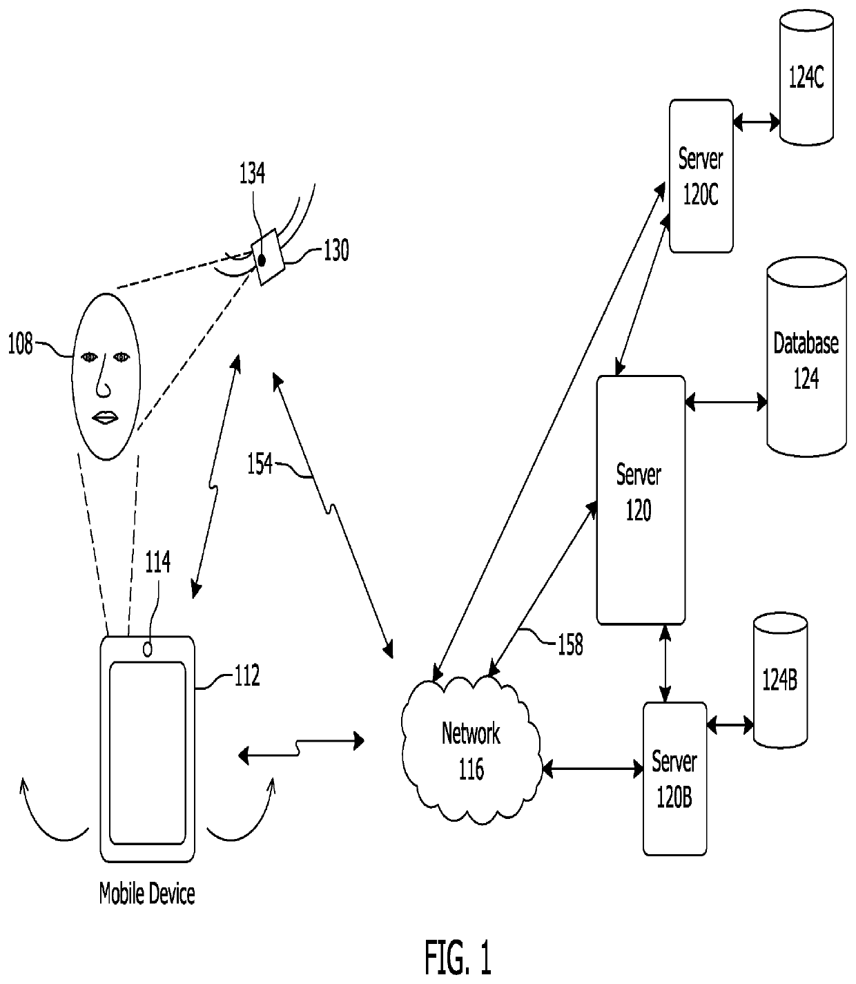
[0067]FIG. 1 illustrates an example environment of use of the facial recognition authentication system described herein. This is but one possible environment of use and system. It is contemplated that, after reading the specification provided below in connection with the figures, one of ordinary skill in the art may arrive at different environments of use and configurations.

[0068]In this environment, a user 108 may have a mobile device 112 which may be used to access one or more of the user's accounts via authentication systems. A user 108 may have a mobile device 112 that can capture a picture of the user 108, such as an image of the u...


PUM


Abstract

Systems and methods for authenticating a user in an authentication system using a computing device configured to capture authentication biometric identity information. The authentication biometric identify information captured during an authentication session. The authentication biometric identify information may comprise or be derived from one or more images of the user being authenticated. The authentication biometric identify information is compared to root identify biometric information. The root identify biometric information is captured from a trusted source, such as trusted devices located at trusted locations, such as a government entity, financial institution, or business. Identity verification may occur by comparing the trusted root identify biometric information to the biometric identify information captured during an authentication session. Liveness determination may also occur to verify the user is a live person. Liveness determination may include comparing two images of the user such that the two images are captured at different distances from the user.

Description

1. PRIORITY CLAIM[0001]This application claims priority to and the benefit of U.S. Provisional Patent Application No. 62 / 621,504 filed Jan. 24, 2018. This application is a continuation in part of U.S. application Ser. No. 15 / 934,105 filed on Mar. 23, 2018 and U.S. application Ser. No. 15 / 900,681 filed on Feb. 20, 2018, both of which are a continuation of and claim priority to U.S. application Ser. No. 14 / 839,505 filed on Aug. 28, 2015, which application claims priority to U.S. Provisional Patent Application No. 62 / 188,584 filed on Jul. 3, 2015; U.S. Provisional Patent Application No. 62 / 139,558 filed on Mar. 27, 2015; U.S. Provisional Patent Application No. 62 / 101,317 filed on Jan. 8, 2015; U.S. Provisional Patent Application No. 62 / 085,963 filed on Dec. 1, 2014; U.S. Provisional Patent Application No. 62 / 064,415 filed on Oct. 15, 2014; U.S. Provisional Patent Application No. 62 / 054,847 filed on Sep. 24, 2014; U.S. Provisional Patent Application No. 62 / 043,224 filed Aug. 28, 2014, t...

Claims


Application Information

Patent Timeline
Patent Type & Authority Patents(United States)
IPC IPC(8): G06F21/32H04W12/06G07C9/00G06Q20/40G06F21/34G06K9/00G06K9/22G06Q20/32H04L29/06H04W12/00H04W88/02
CPCG06K9/00912G06K9/00892G06Q20/3276G07C9/00G06Q20/40145G06K9/22G06K9/00255G06K9/00288G06F21/34H04W12/06G06F21/32G06K9/00926G06K9/00335H04L63/0861H04W88/02H04W12/00508H04W12/68G06V40/172G06V10/17G06V40/50G06V40/67G06V40/70G06V40/166G06V40/20
Inventor TUSSY, KEVIN ALAN
Owner FACETEC INC
Learn More