Gate driver on array circuit and liquid crystal display with the same

a technology of array circuit and gate driver, which is applied in the direction of instruments, static indicating devices, etc., can solve the problems of more power consumption as well, and achieve the effects of enhancing reliability of goa circuit, lowering power consumption of liquid crystal panel, and prolonging the life of goa circui

Active Publication Date: 2020-06-30
TCL CHINA STAR OPTOELECTRONICS TECH CO LTD
View PDF23 Cites 0 Cited by
  • Summary
  • Abstract
  • Description
  • Claims
  • Application Information

AI Technical Summary

Benefits of technology

[0004]An object of the present disclosure is to propose a gate driver on array (GOA) circuit and a liquid crystal display (LCD) with the GOA circuit. In the present disclosure, the conducted time when a square-wave signal is fed to a thin-film transistor (TFT) of a pull-down maintaining circuit in the GOA circuit is shortened to inhibit the aging speed of the TFTs and reduce power consumption, thereby enhancing reliability of the GOA circuit and lowering the power consumption of the liquid crystal panel.
[0016]Compared with the GOA circuit of the related art, new TFTs are respectively added to an input terminal of a twelfth TFT T51 and an input terminal of a thirteenth TFT T52 in the pull-down maintaining circuit in the GOA circuit proposed by the present disclosure. Gates of the new added TFTs both receive a clock signal. Drains of the new added TFTs receive a square-wave signal respectively. In this way, the conducted time when the pull-down maintaining circuit in the GOA circuit receives the square-wave signals of the TFTs is shortened to inhibit the aging speed of the TFTs, and the lifespan of the GOA circuit is prolonged, thereby enhancing reliability of the GOA circuit and lowering the power consumption of the liquid crystal panel.

Problems solved by technology

More power consumes as well.

Method used


Image

  • Gate driver on array circuit and liquid crystal display with the same
  • Gate driver on array circuit and liquid crystal display with the same
  • Gate driver on array circuit and liquid crystal display with the same

Examples


Embodiment Construction

[0024]A gate driver on array (GOA) circuit and a liquid crystal display (LCD) with the GOA circuit proposed by the present disclosure are detailed with the attached figures.

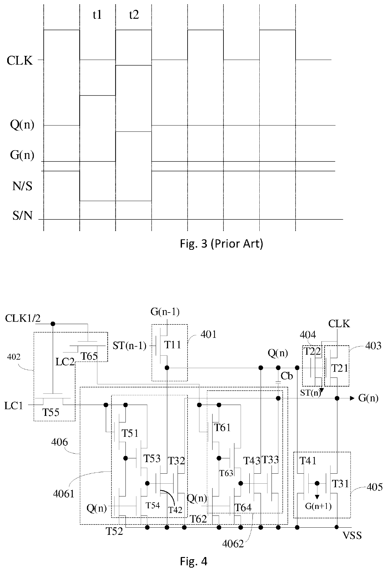
[0025]Please refer to FIG. 4 and FIG. 6. A GOA circuit is proposed by a first embodiment of the present disclosure. The GOA circuit may apply to a liquid crystal panel. The GOA circuit (i.e., a gate driving circuit) includes a plurality of cascaded GOA unit circuits. Each of the plurality of cascaded GOA unit circuits at each stage receives a corresponding clock signal. The GOA circuit includes two clock signals, a first clock signal CLK1 and a second clock signal CLK2, in the first embodiment. Each of the clock signals includes a first high voltage level VGH and a first low voltage level VGL. The first clock signal CLK1 receives a first, third, fifth, . . . , (2k+1)th stage GOA unit circuit, and the second clock signal CLK2 receives a second, fourth, sixth, . . . , (2k+2)th stage GOA unit circuit where k is an i...


PUM


Abstract

A gate driver on array (GOA) circuit includes cascaded GOA unit circuits. An nth stage GOA unit circuit includes a clock signal source, a constant voltage supply, a pull-up control circuit, a pull-up circuit, a downlink circuit, a pull-down circuit, a pull-down maintaining circuit, a bootstrap capacitor and a conducting control circuit. An output terminal of the pull-up control circuit is electrically connected to the pull-up circuit, the downlink circuit, the pull-down circuit, the pull-down maintaining circuit, and the bootstrap capacitor. The constant voltage supply is electrically connected to the pull-down maintaining circuit and the pull-down circuit. The clock signal source is electrically connected to the pull-up circuit, the downlink circuit, and the conducting control circuit. The conducting control circuit is electrically connected to the pull-down maintaining circuit.

Description

BACKGROUND1. Field of the Disclosure[0001]The present disclosure relates to the field of a liquid crystal panel technique, and more particularly, to a gate driver on array (GOA) circuit and a liquid crystal display (LCD) with the GOA circuit.2. Description of the Related Art[0002]A trend of a liquid crystal display (LCD) is to utilize a narrow bezel, to be thin, and low cost. A gate driver on array (GOA) technique is important for such a development tendency. A scanning line driving circuit is integrated on an array substrate of a liquid crystal panel with the GOA technique, thereby reducing the production cost from the materials and manufacturing processes.[0003]FIG. 1 is a circuit diagram of a GOA circuit of the related art. The GOA circuit of the related art includes a control circuit 101, a pull-up circuit 102, a pull-down circuit 103, and a pull-down maintaining circuit 104. Further, the pull-down maintaining circuit 104 includes a first pull-down maintaining circuit 1041 and a...

Claims


Application Information

Patent Timeline
Patent Type & Authority Patents(United States)
IPC IPC(8): G09G3/36
CPCG09G3/3677G09G2310/08G09G2330/021G09G2310/06G09G2320/043G09G2300/0408
Inventor XU, XIANGYANG
Owner TCL CHINA STAR OPTOELECTRONICS TECH CO LTD
Why Eureka
Try Eureka