Devices and methods for managing chest drainage

a technology for chest drainage and devices, applied in the field of wound and surgical drainage, can solve the problems of obstructing the chest tube, 36% of cardiac surgery patients experiencing chest tube clogging, and the current chest tube system suffers from two major flaws, so as to reduce or eliminate the pooling of blood/liquid and/or clogging/clotting

Active Publication Date: 2020-07-07
CENTESE INC
View PDF45 Cites 6 Cited by
  • Summary
  • Abstract
  • Description
  • Claims
  • Application Information

AI Technical Summary

Benefits of technology

[0007]A chest drainage system is needed which reduces or eliminates pooling of blood / liquid and / or clogging / clotting in the drainage tube.
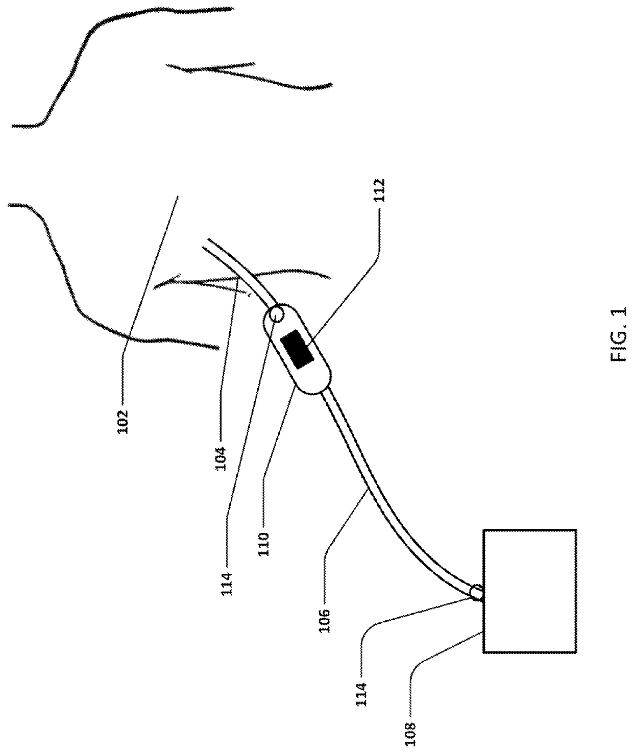
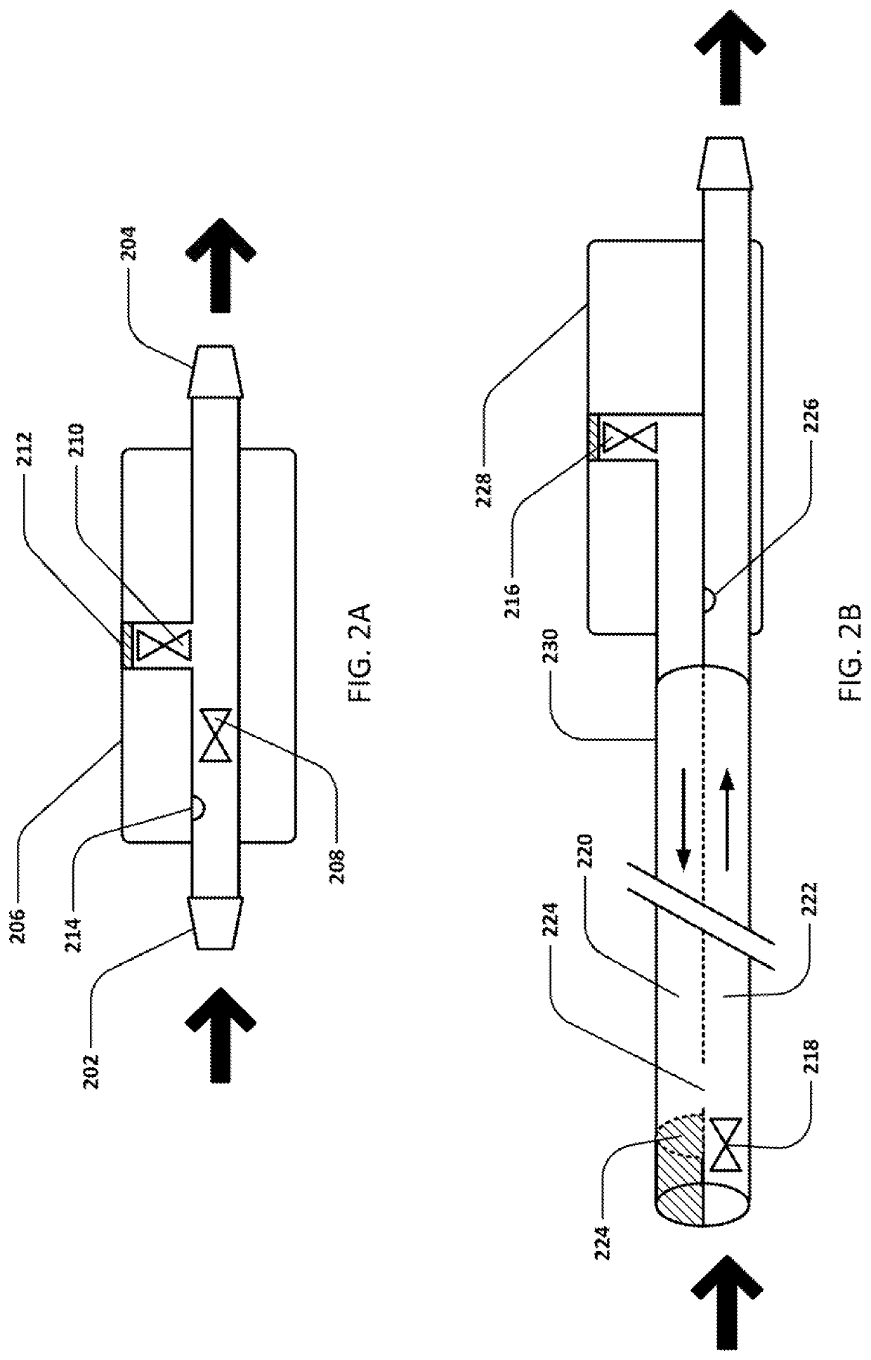
[0008]One embodiment of the drainage system may generally comprise a suction device configured to generate a negative pressure, a first lumen body configured for insertion into a patient body, a second lumen body fluidly coupled to the suction device, a valve assembly fluidly coupled to the first lumen body and to the second lumen body, wherein the valve assembly includes at least a first valve having a closed configuration where the negative pressure generated by the suction device is maintained within the second lumen body, and the first valve further having an open configuration where the negative pressure draws air from an environment and through the second lumen body, a pressure sensor in communication with the first lumen body, and a controller in communication with the pressure sensor, wherein the controller is programmed to sense for a decrease in the negative pressure indicative of an obstruction within the second lumen body, wherein the controller is further programmed to actuate the first valve into the open configuration upon sensing the decrease to clear the obstruction. In another embodiment, the valve may have certain mechanical characteristics, including but not limited to crack pressure, such that it automatically open when the negative pressure decreases a certain amount, eliminating the need for the pressure sensor and controller.
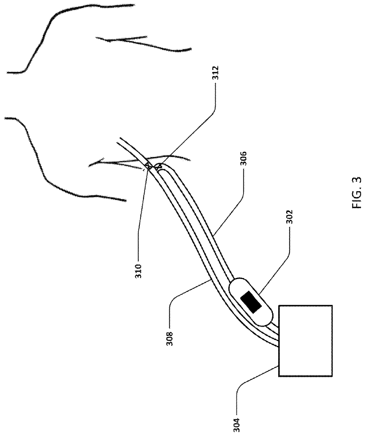
[0009]Another embodiment of the drainage system may generally comprise a suction device configured to generate a negative pressure, a first lumen body configured for insertion into a patient body, a second lumen body fluidly coupled to the suction device, a valve assembly fluidly coupled to the first lumen body and to the second lumen body, wherein the valve assembly includes at least a first valve having a closed configuration where the negative pressure generated by the suction device is maintained within the second lumen body, and the first valve further having an open configuration where the negative pressure draws air from an environment and through the first lumen body, a pressure sensor in communication with the first lumen body, and a controller in communication with the pressure sensor, wherein the controller is programmed to sense for a decrease in the negative pressure indicative of an obstruction within the first lumen body, wherein the controller is further programmed to actuate the first valve into the open configuration upon sensing the decrease to clear the obstruction. In another embodiment, the valve may have certain mechanical characteristics, including but not limited to crack pressure, such that it automatically open when a certain pressure differential exists between the first and second lumen bodies, eliminating the need for the pressure sensor and controller.
[0010]In one exemplary method of use, the method for draining a body lumen ma generally comprise applying a negative pressure to a first lumen body inserted into a patient body, drawing a fluid from the patient body via the first lumen body and through a second lumen body in fluid communication with the first lumen body, monitoring via a pressure sensor for a decrease in the negative pressure as indicative of an obstruction within the second body lumen, actuating a valve assembly coupled to the first lumen body and to the second lumen body upon detecting the decrease such that at least a first valve in the valve assembly actuates from a closed configuration, where the negative pressure is maintained within the second lumen body, and into an open configuration, where the negative pressure draws air from an environment and through the second lumen body, and clearing an obstruction from the second lumen body via the air introduced into the second lumen body. In another exemplary method of use, the valve may automatically open when the negative pressure decreases by a certain amount, eliminating the need to monitor pressure and actuate the valve.
[0011]In another exemplary method of use, the method for draining a body lumen may generally comprise applying a negative pressure to a first lumen body inserted into a patient body, drawing a fluid from the patient body via the first lumen body and through a second lumen body in fluid communication with the first lumen body, monitoring via a pressure sensor for a decrease in the negative pressure as indicative of an obstruction within the first body lumen, actuating a valve assembly coupled to the first lumen body and to the second lumen body upon detecting the decrease such that at least a first valve in the valve assembly actuates from a closed configuration, where the negative pressure is maintained within the second lumen body, and into an open configuration, where the negative pressure draws air from an environment and through the first lumen body, and clearing an obstruction from the first lumen body via the air introduced into the first lumen body. In another exemplary method of use, the valve may automatically open when a pressure differential exists between the first and second lumen bodies eliminating the need to monitor pressure and actuate the valve.

Problems solved by technology

Despite their benefits, current chest tube systems suffer from two major flaws.
Second, clogs can form that obstruct the chest tube, which prevent the negative pressure from being transmitted to the chest and inhibit drainage.
In fact, 36% of cardiac surgery patients experience chest tube clogging.
When proper drainage is inhibited due to these factors, patients are at increased risk for accumulation of fluid around the heart, known as pericardial tamponade, which results in shock and can be fatal.
Additionally, the lungs may be compressed, which can lead to respiratory compromise and be fatal as well.
However, this is nearly impossible in practice, as some slack is required to prevent accidental dislodging of the tube from the body.
However, these methods have not been shown to be effective at improving chest tube suction or drainage.
In fact, stripping has actually been discouraged because it is possible to create extremely high negative pressures (up to −370 cmH2O) that may damage the tissue.

Method used


Image

  • Devices and methods for managing chest drainage
  • Devices and methods for managing chest drainage
  • Devices and methods for managing chest drainage

Examples


Embodiment Construction

[0026]Disclosed is a chest drainage system which reduces or eliminates pooling of blood / liquid and / or clogging / clotting in the drainage tube.

[0027]The chest drainage system continuously monitors chest tube status and clears pooled liquid when necessary to restore negative pressure to the chest. The system may include a valve device which is located between the patient's chest tube and drainage tube and may be used with any standard chest tube. The chest drainage system also includes a controller for monitoring the pressure at or near the valve device and / or at or near the suction device, and possibly a pump for assisting in clearance of pooled liquid and / or clots. The controller may also control the valve device and / or suction device in response to pressure signals. The chest drainage system performs four primary functions:

[0028]1. The chest drainage system detects pooled liquid in the drainage tube by monitoring the pressure near the patient-external end of the chest tube. Pooled l...


PUM


Abstract

Disclosed is a chest drainage system which reduces or eliminates pooling of blood / liquid and / or clogging / clotting in the drainage tube. Generally, the chest drainage system continuously monitors chest tube status and clears pooled liquid when necessary to restore negative pressure to the chest. The system may include a valve device which is located between the patient's chest tube and drainage tube and may be used with any standard chest tube. The chest drainage system also includes a controller for monitoring the pressure at or near the valve device and / or at or near the suction device, and possibly a pump for assisting in clearance of pooled liquid and / or clots. The controller may also control the valve device and / or suction device in response to pressure signals.

Description

CROSS-REFERENCE TO RELATED APPLICATIONS[0001]This application is a continuation of International Patent Application No. PCT / US2015 / 052960 filed Sep. 29, 2015, which claims the benefit of priority to U.S. Provisional Application No. 62 / 056,683 filed Sep. 29, 2014 and U.S. Provisional Application No. 62 / 136,488 filed Mar. 21, 2015 and U.S. Provisional Application No. 62 / 149,559 filed Apr. 18, 2015 and U.S. Provisional Application No. 62 / 181,031 filed Jun. 17, 2015, each of which is incorporated herein by reference in its entirety.FIELD OF THE INVENTION[0002]The present invention relates to wound and surgical drainage.INCORPORATION BY REFERENCE[0003]All publications and patent applications mentioned in this specification are herein incorporated by reference to the same extent as if each such individual publication or patent application were specifically and individually indicated to be so incorporated by reference.BACKGROUND OF THE INVENTION[0004]Chest tubes are required anytime air or...

Claims


Application Information

Patent Timeline
Patent Type & Authority Patents(United States)
IPC IPC(8): A61M1/00A61M27/00A61M25/00
CPCA61M1/0078A61M1/0035A61M27/00A61M2025/0019A61M2205/50A61M2205/3344A61M2205/106A61M2205/52A61M2205/502A61M2210/101A61M2205/3337A61M1/742A61M1/743A61M1/83
Inventor LUXON, EVAN S.BURNETT, DANIEL R.ZIEGLER, MARK
Owner CENTESE INC
Why Eureka
Try Eureka