
System, method, and computer program product for over-constraint/deadcode detection in a formal verification

a formal verification and over-constraint technology, applied in the field of electronic design verification, can solve the problems of introducing compiler performance degradation, high code maintenance cost of the approach, and dead code in register transfer

Active Publication Date: 2020-07-07
CADENCE DESIGN SYST INC
View PDF19 Cites 2 Cited by
  • Summary
  • Abstract
  • Description
  • Claims
  • Application Information

AI Technical Summary

Benefits of technology

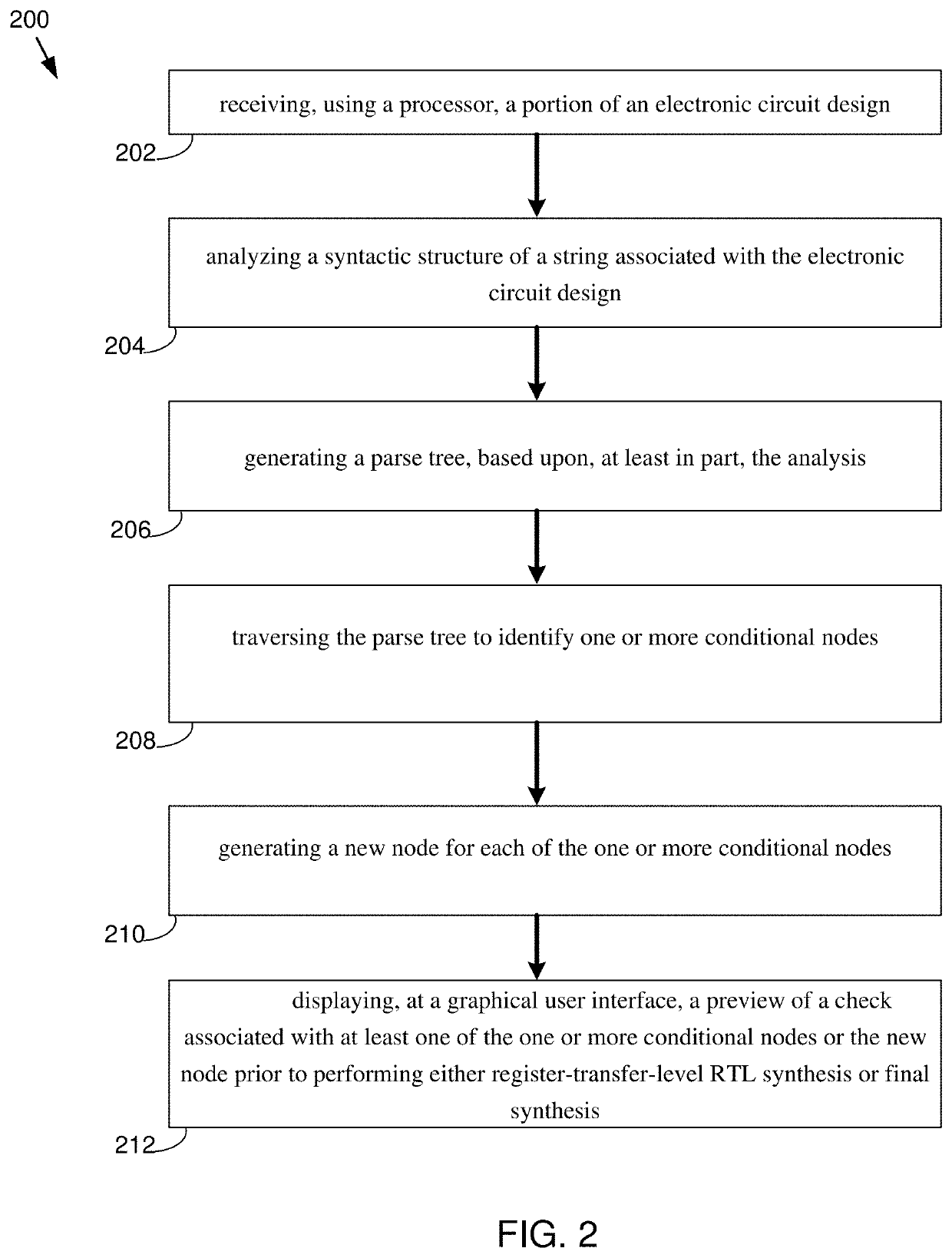
The present patent provides a computer-implemented method for verifying the design of an electronic circuit using a computer-readable storage medium and a graphical user interface. The method involves analyzing the structure of a string associated with the circuit design, generating a parse tree based on the analysis, and identifying conditional nodes in the tree. The method also allows users to filter out deadcode checks. The technical effects of this invention include improved efficiency and accuracy in electronic circuit design verification.

Problems solved by technology

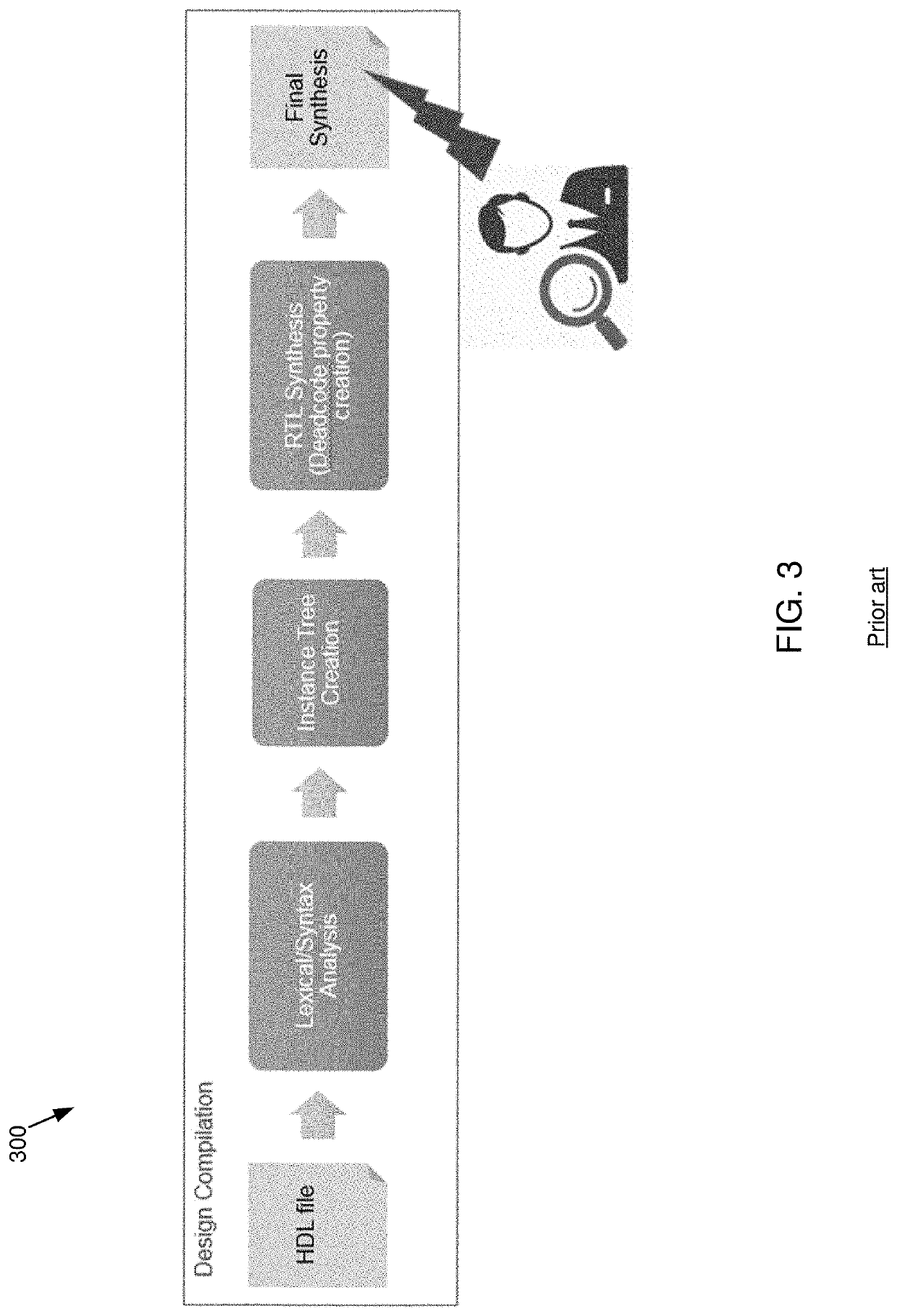
One of the problems that can occur during integrated circuit (“IC”) development is the introduction of deadcode in register-transfer-level (“RTL”), that is, a logic inside the circuit that will never be reached during operation.
This might be introduced, for example, due to design constraints.
There are different methods to discover deadcode using simulation, but they are costly since the discovery process must do exhaustive searches into the RTL.
However, this approach also has a high code maintenance cost since it is intrusive to the compilation process, inserts duplicated logic, is error prone, and may introduce compilation performance degradation.
Additionally, the user cannot visualize nor interact with these checks until the full design compilation process is completed, which can take hours for large designs.

Method used


Image

  • System, method, and computer program product for over-constraint/deadcode detection in a formal verification
  • System, method, and computer program product for over-constraint/deadcode detection in a formal verification
  • System, method, and computer program product for over-constraint/deadcode detection in a formal verification

Examples


Embodiment Construction

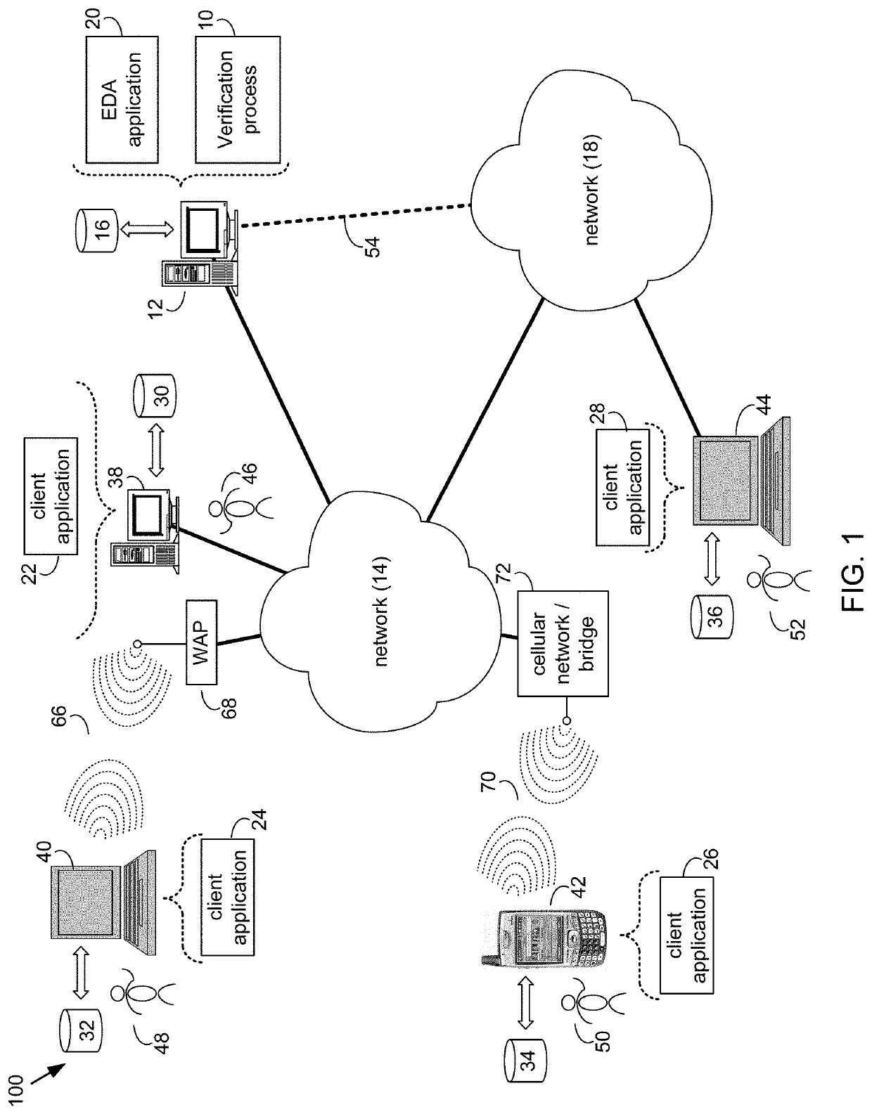
[0030]Reference will now be made in detail to the embodiments of the present disclosure, examples of which are illustrated in the accompanying drawings. The present disclosure may, however, be embodied in many different forms and should not be construed as being limited to the embodiments set forth herein. Rather, these embodiments are provided so that this disclosure will be thorough and complete, and will fully convey the concept of the disclosure to those skilled in the art.

[0031]As will be appreciated by one skilled in the art, the present disclosure may be embodied as a method, system, or computer program product. Accordingly, the present disclosure may take the form of an entirely hardware embodiment, an entirely software embodiment (including firmware, resident software, micro-code, etc.) or an embodiment combining software and hardware aspects that may all generally be referred to herein as a “circuit,”“module” or “system.” Furthermore, the present disclosure may take the fo...


PUM


Abstract

The present disclosure relates to a method for use in the formal verification of an electronic circuit. Embodiments may include receiving, using a processor, a portion of an electronic circuit design and analyzing a syntactic structure of a string associated with the electronic circuit design. Embodiments may also include generating a parse tree, based upon, at least in part, the analysis and traversing the parse tree to identify one or more conditional nodes. Embodiments may further include generating a new node for each of the one or more conditional nodes and displaying, at a graphical user interface, a check, at least one of the one or more conditional nodes or the new node prior to performing either register-transfer-level RTL synthesis or final synthesis.

Description

FIELD OF THE INVENTION[0001]The present disclosure relates to electronic design verification, and more specifically, to a method for over-constraint / deadcode detection in a formal verification.DISCUSSION OF THE RELATED ART[0002]The electronic design automation (“EDA”) market segment is recently growing due to high interest in areas such as mobility, automotive, Internet of Things (“IOT”) and cloud computing. These new opportunities increase the number of new semiconductor-based products developed, and with it, the necessity to test them.[0003]One of the problems that can occur during integrated circuit (“IC”) development is the introduction of deadcode in register-transfer-level (“RTL”), that is, a logic inside the circuit that will never be reached during operation. This might be introduced, for example, due to design constraints. There are different methods to discover deadcode using simulation, but they are costly since the discovery process must do exhaustive searches into the R...

Claims


Application Information

Patent Timeline
Patent Type & Authority Patents(United States)
IPC IPC(8): G06F17/50G06F30/3323G06F30/30G06F30/31G06F30/367G06F30/337G06F30/373G06F30/398
CPCG06F30/3323G06F30/30G06F30/31G06F30/367G06F30/337G06F30/373G06F30/398G06F2111/04
Inventor REZENDE BARBOSA, LUIS HUMBERTODOS SANTOS PEREIRA, RAQUEL LARAFURTADO, CAIO ALVESDIAS VITORINO, BRENO AUGUSTOCREPALDE, MIRLAINE APARECIDADA SILVA MANTINI VIANA, RODRIGOPRATES, LUCAS DUARTE
Owner CADENCE DESIGN SYST INC
Learn More