Attaching objects made of dissimilar materials using a molded attachment block

a technology of dissimilar materials and attachment blocks, which is applied in the direction of manufacturing tools, metal working apparatuses, forms/shuttering/falseworks, etc., can solve the problems of damage to the tile assembly, affecting the aesthetic appearance of the tile assembly, and affecting the strength of the tile assembly

Active Publication Date: 2020-07-14
LINCOLN TIMOTHY MARTIN
View PDF1 Cites 0 Cited by
  • Summary
  • Abstract
  • Description
  • Claims
  • Application Information

AI Technical Summary

Benefits of technology

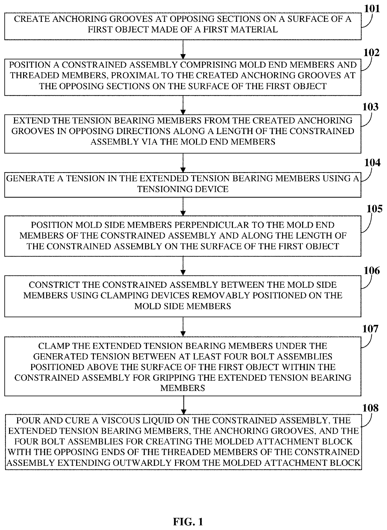
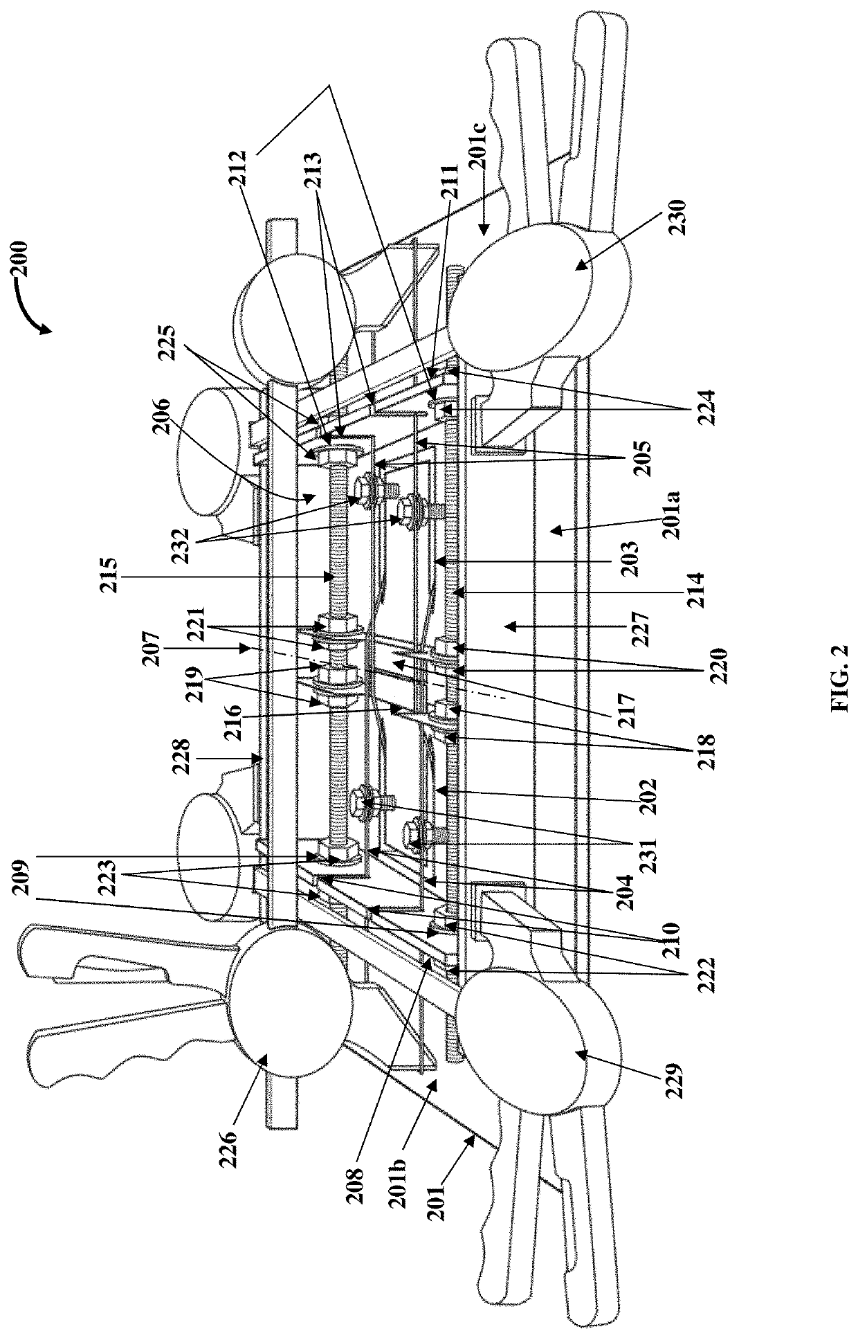
[0005]The method disclosed herein addresses the above recited need for attaching a first object made of a first material to one or more second objects made of one or more of multiple second materials that are dissimilar to the first material of the first object, using a molded attachment block, that is, a modular structure, and without using any bonding material and without damaging the surface and aesthetic appearance of the first object. The method disclosed herein comprises assembling the molded attachment block and attaching one or more second objects made of one or more second materials dissimilar to the first material of the first object, to a surface of the first object using the assembled molded attachment block. The molded attachment block encases mechanical means comprising anchoring grooves, tension bearing members, wire deflector plates, mold end members, threaded members, mold side members, etc., retains tension in the encased mechanical means under different conditions of strain experienced by the mechanical means, and protects the mechanical means from an external environment, thereby reducing time and effort involved in maintenance of each of the mechanical means on a regular basis.
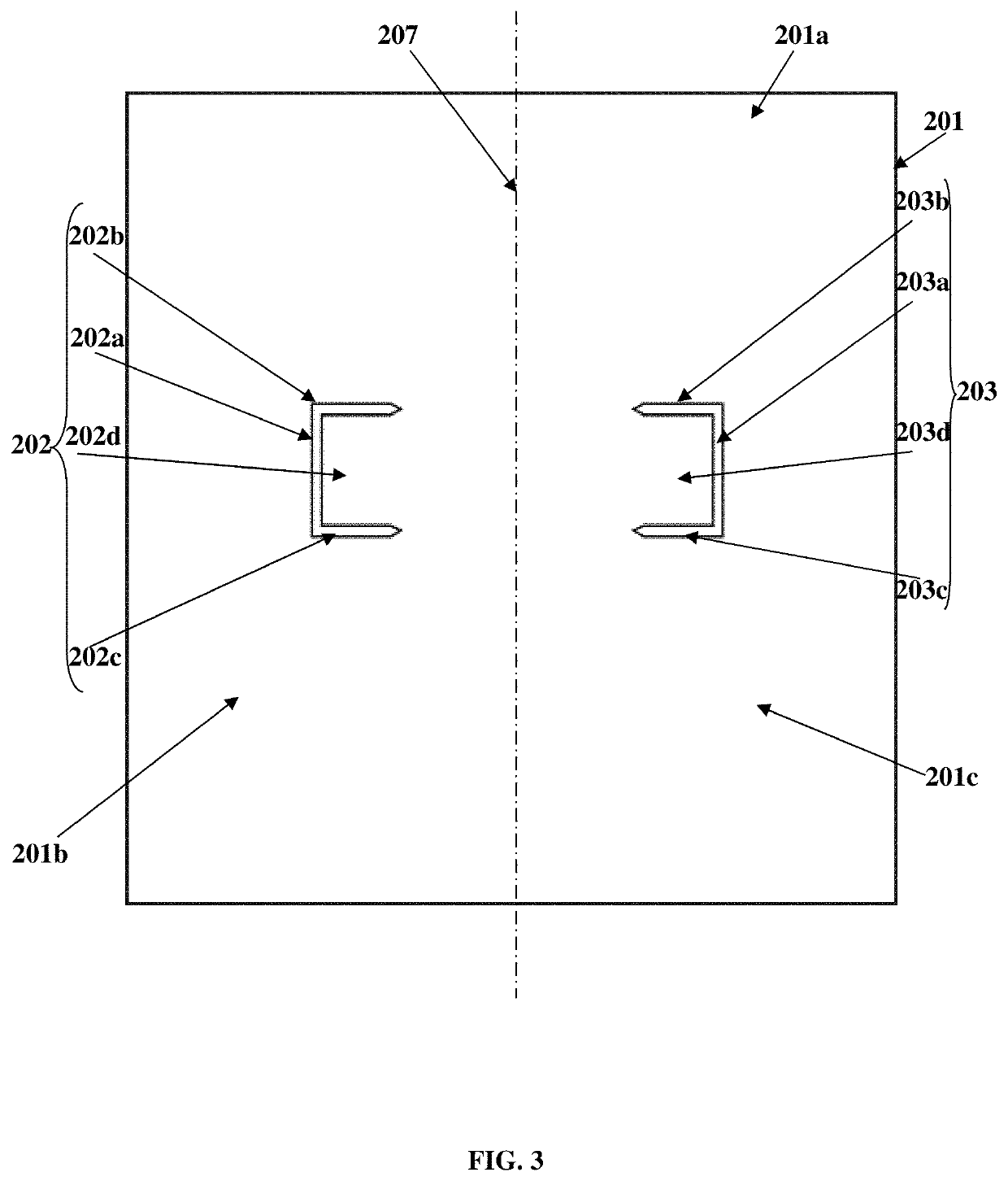
[0006]In the method disclosed herein, anchoring grooves are created at opposing sections on a surface of the first object made of the first material. The anchoring grooves anchor tension bearing members on the first object. A constrained assembly comprising mold end members and threaded members is positioned proximal to the created anchoring grooves at the opposing sections on the surface of the first object. The mold end members comprise openings for receiving and perpendicularly engaging opposing ends of the threaded members. The tension bearing members are extended from the created anchoring grooves in opposing directions along a length of the constrained assembly via the mold end members. A tension is generated in the extended tension bearing members using a tensioning device. Mold side members are positioned perpendicular to the mold end members of the constrained assembly and along the length of the constrained assembly on the surface of the first object. The constrained assembly is constricted between the mold side members using clamping devices that are removably positioned on the mold side members. The extended tension bearing members, under the generated tension, are clamped between at least four bolt assemblies positioned above the surface of the first object within the constrained assembly for gripping the extended tension bearing members. A viscous liquid is poured on the constrained assembly, the extended tension bearing members, the anchoring grooves, and the bolt assemblies, and cured for creating the molded attachment block with the opposing ends of the threaded members of the constrained assembly extending outwardly from the molded attachment block. The clamping devices, and in an embodiment, the mold side members are removed from the created molded attachment block after the poured viscous liquid is cured. Ends of the extended tension bearing members that extend outwardly from the created molded attachment block are cut. The opposing ends of the threaded members extending from the created molded attachment block allow attachment of one or more second objects made of one or more second materials dissimilar to the first material of the first object to the surface of the first object without any bonding material.

Problems solved by technology

Over time, the tile assembly may lose its strength due to a change in the properties of the bonding material caused, for example, by a change in climate, a corrosive environment, or variable loads.
Replacing the bonding material or clipping the tiles may damage the tile assembly or mar the aesthetic appearance of the tile assembly.
However, the mechanical means, for example, ridges, grooves, clips, screws, bolts, nails, etc., may also damage the objects, for example, the tiles, and mar the aesthetic appearance of the tiles.
Moreover, the mechanical means are typically exposed to an external environment and require continuous maintenance.

Method used


Image

  • Attaching objects made of dissimilar materials using a molded attachment block
  • Attaching objects made of dissimilar materials using a molded attachment block
  • Attaching objects made of dissimilar materials using a molded attachment block

Examples


Embodiment Construction

[0027]FIG. 1 illustrates a method for attaching a first object 201 exemplarily illustrated in FIGS. 2-4 and FIGS. 7-18, made of a first material to one or more second objects made of one or more of multiple second materials dissimilar to the first material of the first object 201, without any bonding material, for example, an adhesive, a chemical bonding material, etc., using a molded attachment block 1601 exemplarily illustrated in FIGS. 16A-16B. As used herein, “first object” refers to any tangible article or item, for example, a tile, a block, a pipe, etc., made of a first material that can be attached to another object, that is, a second object made of a second material similar or dissimilar to the first material. The first object 201 is, for example, a flat object, a cylindrical object, or any object having a constant surface geometry. As used herein, “constant surface geometry” refers to a geometry where a surface is constant and uniform and does not have abrupt protrusions th...


PUM

PropertyMeasurementUnit
vertical angleaaaaaaaaaa
lengthaaaaaaaaaa
tensionaaaaaaaaaa

Abstract

A method for attaching a first object to one or more second objects of dissimilar materials, without any bonding material, using a molded attachment block is provided. Anchoring grooves are created and a constrained assembly is positioned at opposing sections on a surface of the first object. A tension is generated in tension bearing members anchored in the anchoring grooves and extended along a length of the constrained assembly. The constrained assembly is constricted between mold side members positioned perpendicular to the mold end members. The tension bearing members are clamped between bolt assemblies. A viscous liquid is poured and cured on the constrained assembly, the tension bearing members, the anchoring grooves, and the bolt assemblies for creating the molded attachment block with opposing ends of the threaded members of the constrained assembly extending outwardly from the molded attachment block for attachment to second objects without any bonding material.

Description

BACKGROUND[0001]Objects made of dissimilar materials are typically attached to each other using a bonding material, for example, glue, adhesives, mortar, etc. Consider an example where tiles are attached to a surface, for example, a wall, for covering wall surfaces, for constructing standalone structures to support loads, for partitioning structures, for ornamental purposes, etc. Gaps between adjacent tiles to be attached are filled with the bonding material. The assembly of the adjacent tiles forms a tile assembly that is primarily strengthened by the bonding material. Over time, the tile assembly may lose its strength due to a change in the properties of the bonding material caused, for example, by a change in climate, a corrosive environment, or variable loads. Replacing the bonding material or clipping the tiles may damage the tile assembly or mar the aesthetic appearance of the tile assembly.[0002]To avoid the problems associated with using the bonding material for attaching ob...

Claims


Application Information

Patent Timeline
Patent Type & Authority Patents(United States)
IPC IPC(8): B26B7/00E04C5/08B28B1/26B28B7/00
CPCB28B7/0014B28B1/266E04C5/08E04C5/085B28B2007/005E04F13/0833E04F13/0862E04F13/0891E04F21/023E04G13/00
Inventor LINCOLN, TIMOTHY MARTIN
Owner LINCOLN TIMOTHY MARTIN
Why Eureka
Try Eureka