
Vehicle cooling air introduction structure

a technology for introduction structure and cooling air, which is applied in the direction of mechanical equipment, machines/engines, transportation and packaging, etc., can solve the problems of increasing the number of parts and the space for installing them in the body, and achieve the effect of increasing the number of parts and efficient supply

Active Publication Date: 2021-08-05
TOYOTA JIDOSHA KK
View PDF0 Cites 0 Cited by
  • Summary
  • Abstract
  • Description
  • Claims
  • Application Information

AI Technical Summary

Benefits of technology

This disclosure is about a structure for efficiently supplying cooling air to a vehicle's radiator while keeping the number of parts low. The structure includes a cover member that covers the front of the radiator and an opening member that can move back and close off an open portion formed at the lower end of the cover member. The opening member has a concavo-convex shape to reduce the potential for noise caused by the lower end coming into contact with the upper end of the outer plate member. The structure also ensures that whistling noises at specific resonant frequencies do not occur simultaneously and loudly. Overall, this structure allows for efficient cooling air supply without adding excessive parts to the vehicle.

Problems solved by technology

However, in the case of the above configuration, the grille shutter frame and the pivot shafts that pivotably support the two upper and lower fins become necessary, so space for installing them becomes necessary in the body and the number of parts increases.

Method used


Image

  • Vehicle cooling air introduction structure
  • Vehicle cooling air introduction structure
  • Vehicle cooling air introduction structure

Examples


Embodiment Construction

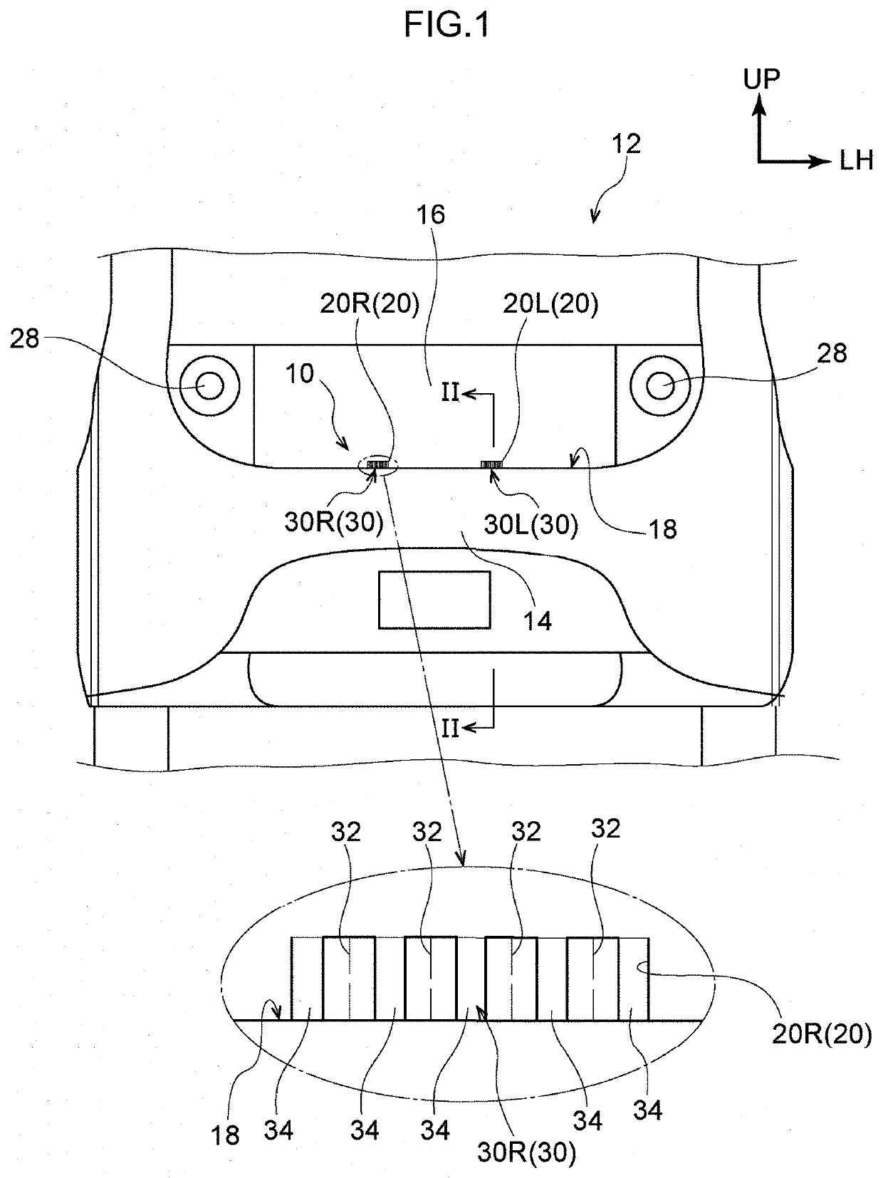
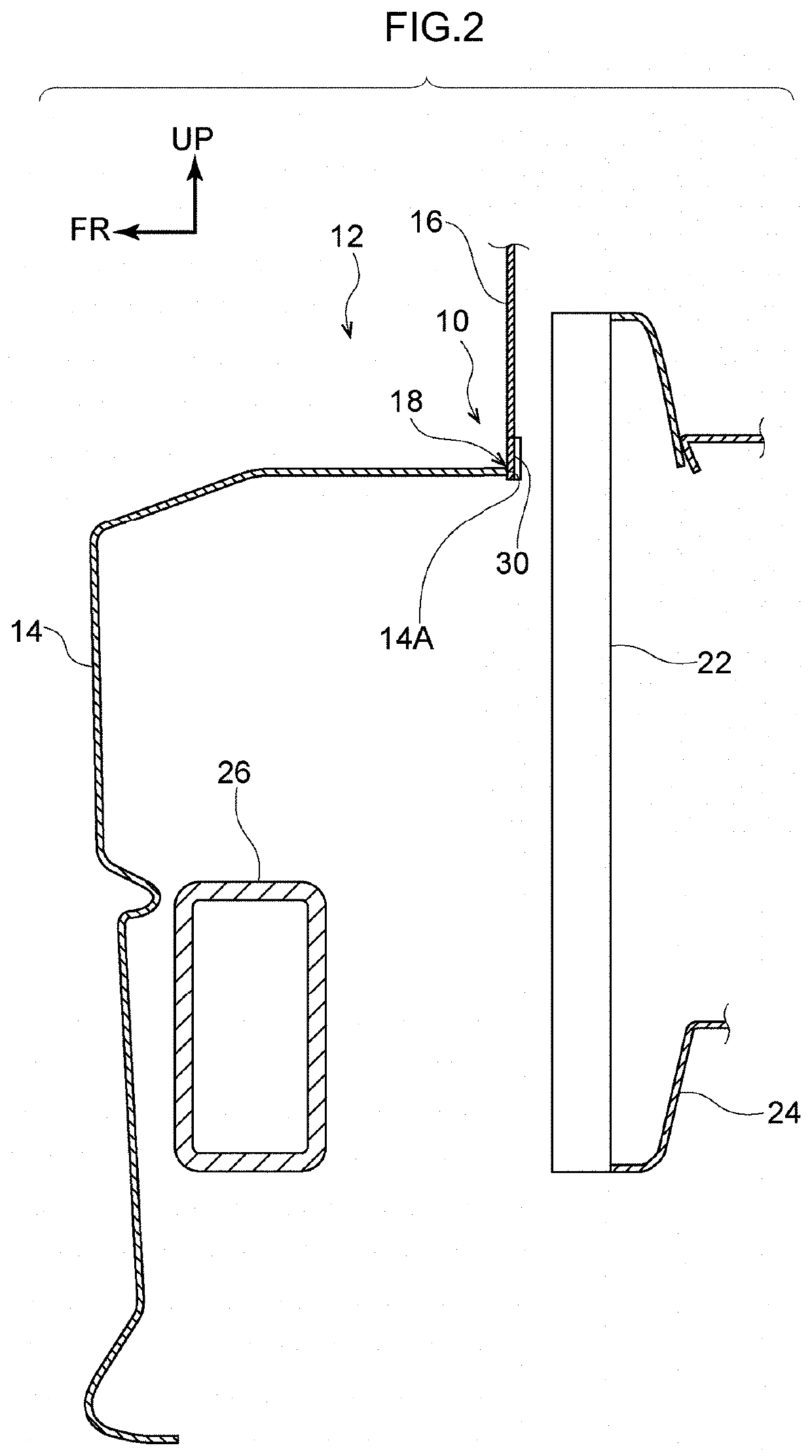
[0024]An embodiment pertaining to this disclosure will be described in detail below based on the drawings. It will be noted that a cooling air introduction structure 10 pertaining to the embodiment is applicable preferably to an electric vehicle serving as a vehicle. Therefore, in the embodiment, a self-driving bus (hereinafter called “the bus”) 12 including a MaaS (Mobility as a Service) vehicle will be taken as an example and described as the electric vehicle (see FIG. 1).

[0025]For convenience of description, arrow UP appropriately shown in the drawings indicates the upward direction, relative to the vehicle body, of the bus 12, arrow FR indicates the forward direction, relative to the vehicle body, of the bus 12, and arrow LH indicates the leftward direction, relative to the vehicle body, of the bus 12. When the directions of upper / lower, front / rear, and right / left are used without further specification in the following description, these will be understood to mean upper / lower in...


PUM


Abstract

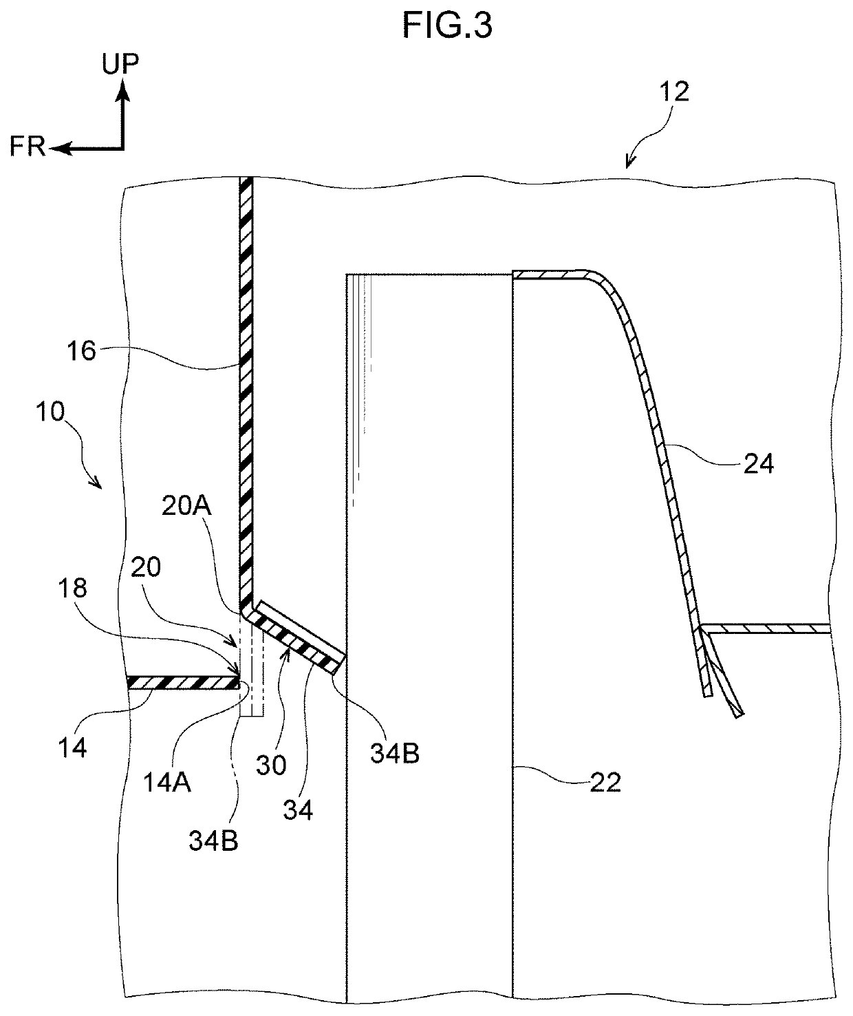
a vehicle cooling air introduction structure includes: an outer plate member that covers a front side, relative to a vehicle body, of a radiator; a cover member that is provided adjacent to an upper side, relative to the vehicle body, of the outer plate member and covers a front upper side, relative to the vehicle body, of the radiator; and an opening member that is moved in a rearward direction, relative to the vehicle body, by wind pressure during travel to thereby open an open portion at a lower end portion of the cover member.

Description

CROSS-REFERENCE TO RELATED APPLICATION[0001]This application is based on and claims priority under 35 USC 119 from Japanese Patent Application No. 2020-017423 filed on Feb. 4, 2020, the disclosure of which is incorporated by reference herein.BACKGROUNDTechnical Field[0002]This disclosure relates to a vehicle cooling air introduction structure.Related Art[0003]There is known a vehicle grille shutter configured to guide cooling air to the upper portion of a radiator, thereby enhancing the ability to cool the upper portion, by changing the directions faced by two upper and lower fins that are attached to a grille shutter frame and that are pivotable about pivot shafts in a horizontal direction (e.g., see Japanese Patent Application Laid-open No. 2019-104449).[0004]However, in the case of the above configuration, the grille shutter frame and the pivot shafts that pivotably support the two upper and lower fins become necessary, so space for installing them becomes necessary in the body a...

Claims


Application Information

Patent Timeline
IPC IPC(8): B60K11/08
CPCB60K11/08B60K11/04B60K11/085Y02T10/88F01P1/00F01P11/10
Inventor MORIMOTO, MASATAKAKITAJIMA, SUSUMU
Owner TOYOTA JIDOSHA KK
Learn More