
Fluid decontamination apparatus

a technology of decontamination apparatus and flue, which is applied in the direction of water treatment temperature conditions, separation processes, and filtration treatment, etc., can solve the problems of further and destruction of unwanted and toxic chemicals

Active Publication Date: 2020-07-14
PONTIC TECH LLC
View PDF17 Cites 1 Cited by
  • Summary
  • Abstract
  • Description
  • Claims
  • Application Information

AI Technical Summary

Benefits of technology

The invention is a fluid decontamination apparatus that uses three-dimensional open structured substrates to help destroy toxic species and organic compounds in contaminated fluids. These substrates are designed to induce turbulent flow and enhance the destruction of harmful chemicals by promoting cavitation and chemical reactions on both their exterior and interior surfaces. The substrates can be coated with catalysts to enhance their ability to initiate chemical reactions and remove specific contaminants from the fluid. The apparatus can be designed in various shapes and sizes to maximize fluid flow and destruction of unwanted contaminants. Overall, this invention provides an effective method for destroying harmful chemicals in contaminated fluids.

Problems solved by technology

The porosity can define a fluid flow path (flow pattern) within the 3DOS substrate that enables extending the volume of a fluid experiencing turbulent flow conditions, and thus increasing the exposure to hydrodynamic cavitation within the fluid, leading to further destruction of unwanted and toxic chemicals.
The 3DOS substrates further provide active sites on its exterior and / or interior surfaces wherein chemical reactions can proceed, also leading to the destruction of unwanted and toxic chemicals.

Method used


Image

  • Fluid decontamination apparatus
  • Fluid decontamination apparatus
  • Fluid decontamination apparatus

Examples


Embodiment Construction

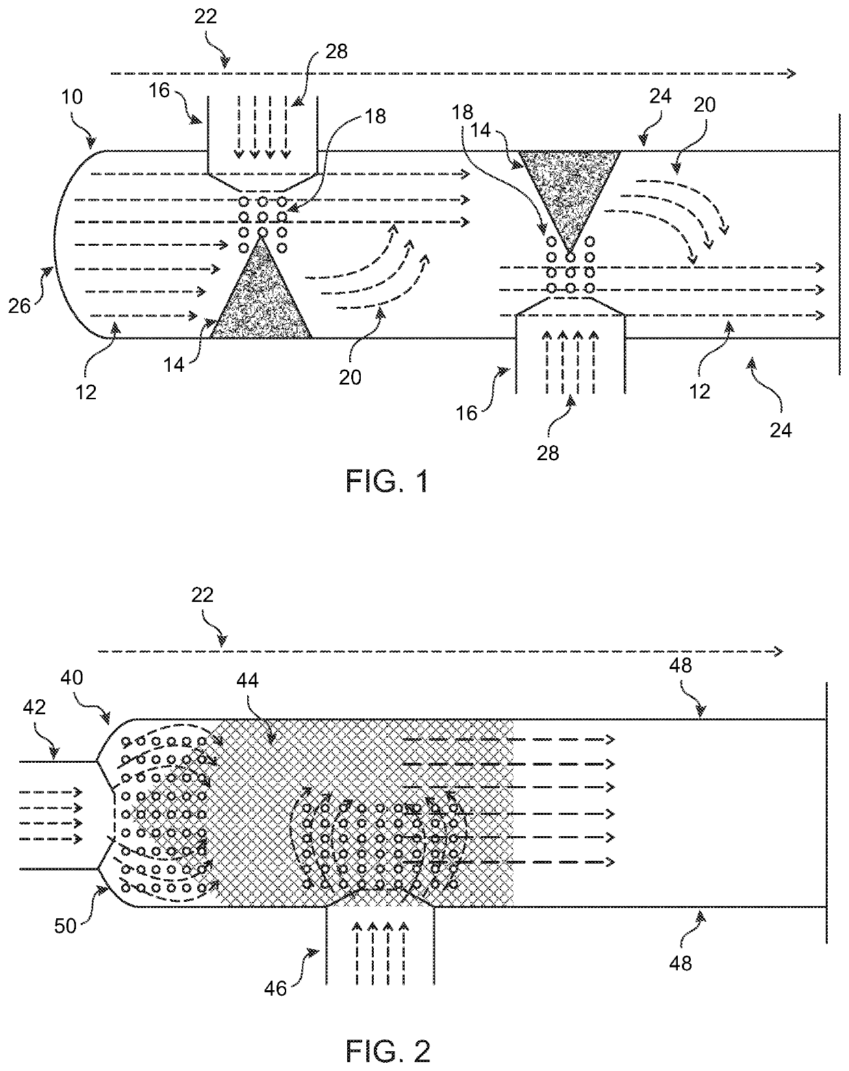
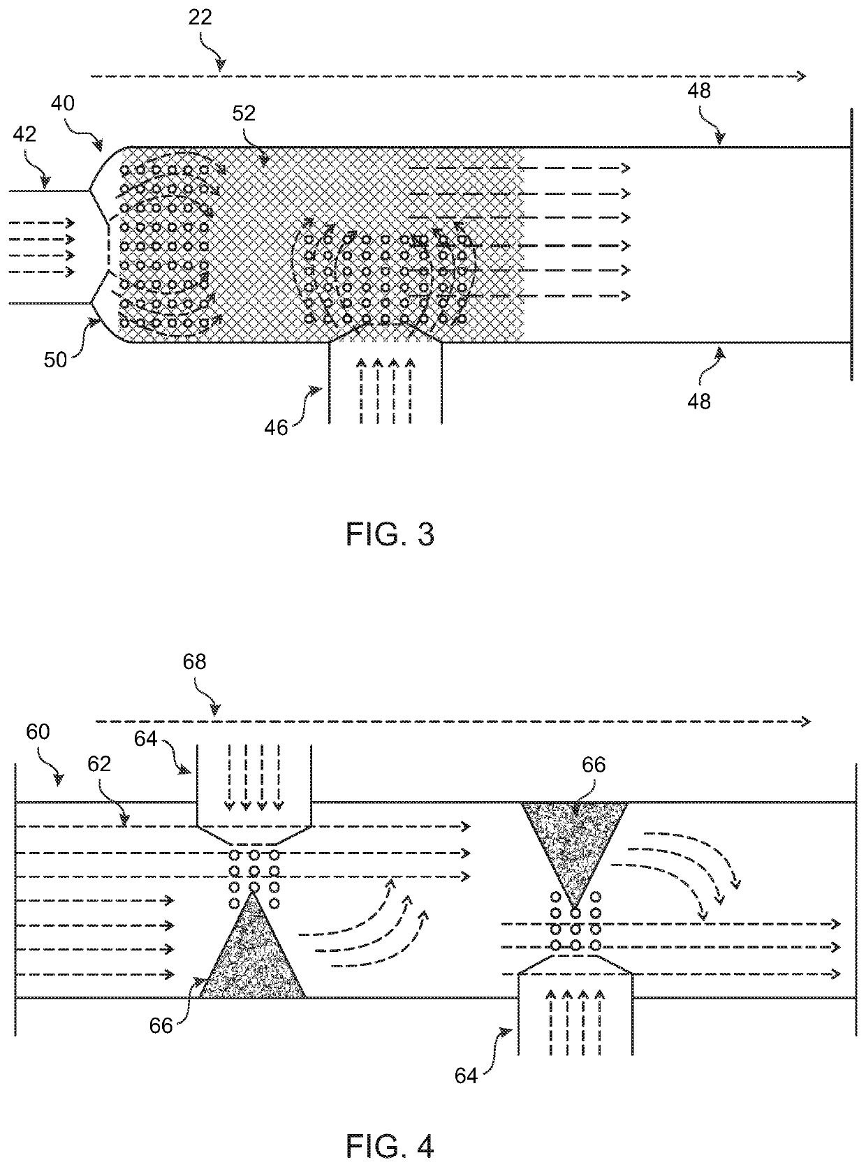
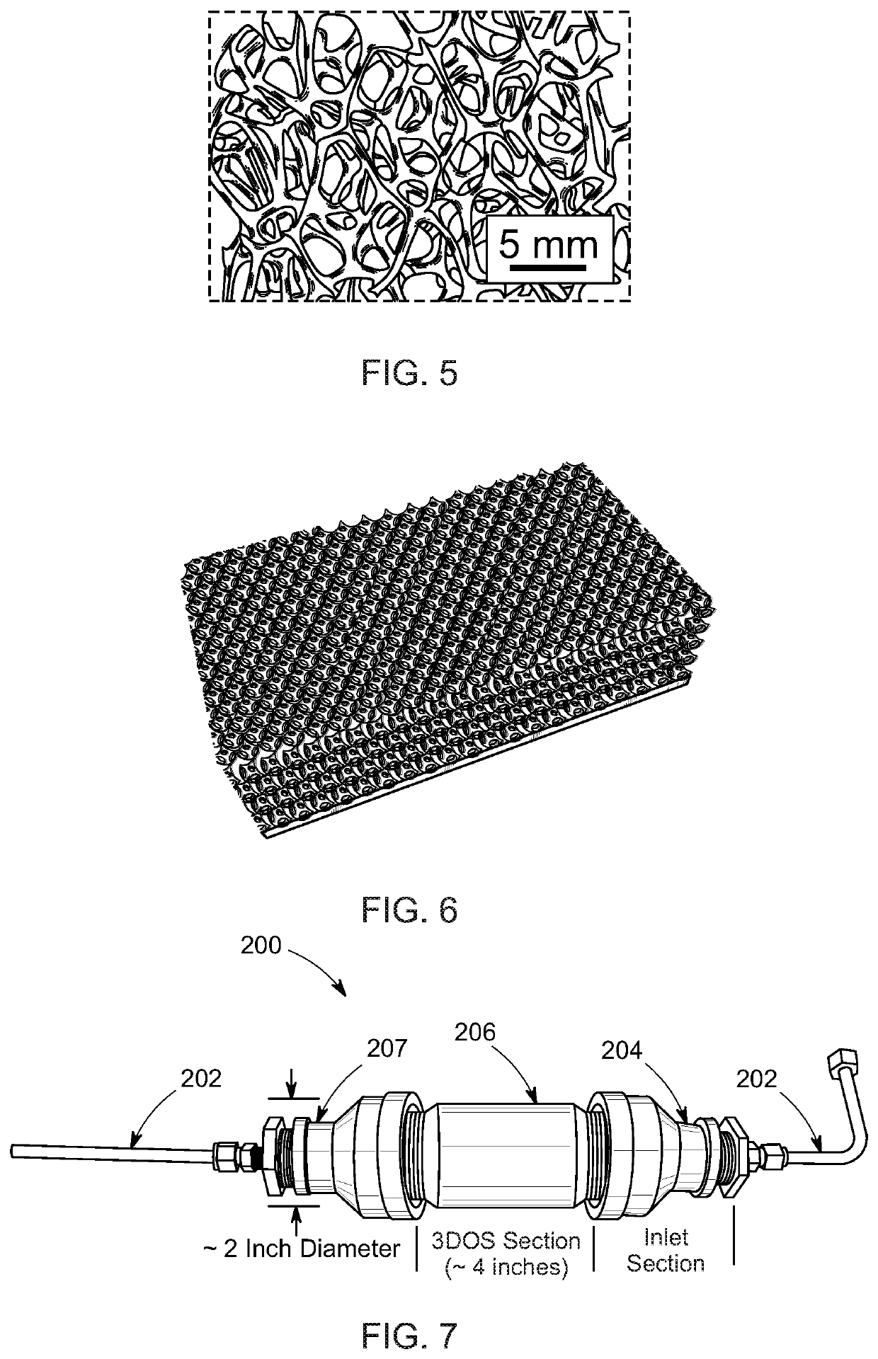
[0039]Referring now to the drawings, and particularly FIG. 1, there is shown a fluid decontamination apparatus having a body 10 with a plurality of three-dimensional open structure (3DOS) substrates 14 spaced about therein, wherein a contaminated fluid flowing 12 through the body 10 will contact the 3DOS substrates 14. Nozzles 16 can be inserted and secured within inlet apertures disposed about the body 10 and configured to inject 28 the contaminated fluid with / without air to induce the occurrence of hydrodynamic cavitation 18. The substrates 14 can be porous and permeable, enabling the contaminated fluid to flow 12 therethrough, wherein the fluid flow passageway through the pores extends the volume of contaminated fluid exposed to turbulent and cavitation inducing flow conditions. Moreover, the 3DOS substrates 14 may be coated with one or more types of catalysts, wherein the interaction between the contaminated fluid and the porous surfaces can initiate chemical reactions. As such,...


PUM

PropertyMeasurementUnit
pressuresaaaaaaaaaa
temperatureaaaaaaaaaa
pressureaaaaaaaaaa

Abstract

A fluid decontamination apparatus is provided having a container body with a plurality of three-dimensional open structure (3DOS) substrates spaced about therein, wherein a contaminated fluid flowing through the container body will contact the 3DOS substrates. Nozzles can be inserted and secured within inlet apertures disposed about the container body, configured to inject the contaminated fluid with / without air to induce the occurrence of hydrodynamic cavitation. The substrates can be porous and permeable enabling the contaminated fluid to flow therethrough, wherein the fluid flow passageway through the pores extends the volume of contaminated fluid exposed to turbulent and cavitation inducing flow conditions. Moreover, the 3DOS substrates may be coated with one or more types of catalysts so as to initiate chemical reactions. As such, the extended exposure of the contaminated fluid to hydrodynamic cavitation forming conditions, along with the chemical reactions carried out on the porous surfaces, enable an increased number of toxic species and unwanted organic compounds to be destroyed and / or altered, thereby enhancing the decontamination of the flowing fluid.

Description

CROSS REFERENCE TO RELATED APPLICATION[0001]This application claims the benefit of U.S. Provisional App. No. 62 / 587,043, filed Nov. 16, 2017, and U.S. Provisional App. No. 62 / 641,677, filed Mar. 12, 2018, which are incorporated by reference.FIELD OF THE INVENTION[0002]The present invention relates generally to fluid decontamination and, more particularly, to the use of three dimensionally open structured material to enhance existing fluid decontamination methods.BACKGROUND OF THE INVENTION[0003]Fluids, particularly liquids such as water, are susceptible to being contaminated with toxic species and other unwanted organic compounds. As such, there are several methods used in various industries to decontaminate and treat such contaminated fluids. These methods include sonication, hydrodynamic cavitation and / or the use of chemical reactions, particularly aided with a catalyst.[0004]However, several of these existing methods are often limited in their effectiveness due to physical and / or...

Claims


Application Information

Patent Timeline
Patent Type & Authority Patents(United States)
IPC IPC(8): B01D46/00C02F1/32C02F1/00B01F5/06C02F1/36C02F1/72C02F101/30
CPCC02F1/725C02F1/36B01D46/0054B01D46/0002C02F1/325C02F1/001C02F2301/02C02F2301/06C02F2301/10C02F2201/3227C02F2201/002C02F2101/30B01F5/0695Y02A50/20C02F1/281C02F2305/023C02F2305/10C02F2301/028B01F25/4524
Inventor VOECKS, GERALD
Owner PONTIC TECH LLC
Learn More