
Ventilator mounting bracket

a technology for mounting brackets and ventilators, which is applied in the direction of ventilation systems, lighting and heating apparatus, heating types, etc., can solve the problems of affecting the flexibility of use of mounting brackets and difficult installation, and achieve the effects of reducing installation time and installation cost, convenient and efficient installation, and large adjustable distance rang

Active Publication Date: 2020-07-14
AUPU HOME STYLE CORP LTD
View PDF22 Cites 0 Cited by
  • Summary
  • Abstract
  • Description
  • Claims
  • Application Information

AI Technical Summary

Benefits of technology

The present invention provides a ventilator mounting bracket that can be easily and efficiently installed in new and old houses, has a relatively large adjustable distance range, can ensure that ventilators can be installed at any position, and can reduce the installation time and installation cost of the ventilators. The mounting bracket is conveniently and effectively installed, can be folded and telescoped to increase the flexibility of controllability thereof, and makes installation convenient.

Problems solved by technology

Through analysis on the usage and efficiency of existing mounting brackets, it is found that some mounting brackets have defects such as difficult installation and fixation, that some mounting brackets can be used during decoration of only new houses or can be used only after the existing ceiling opening sizes are changed during renovation of old houses, and that some mounting brackets apply to certain fixed positions or are small in adjustable distance range during installation.
The flexibility of use of the mounting brackets is affected.

Method used


Image

  • Ventilator mounting bracket
  • Ventilator mounting bracket
  • Ventilator mounting bracket

Examples


Embodiment Construction

[0057]The present invention is described in further detail in conjunction with the attached drawings.

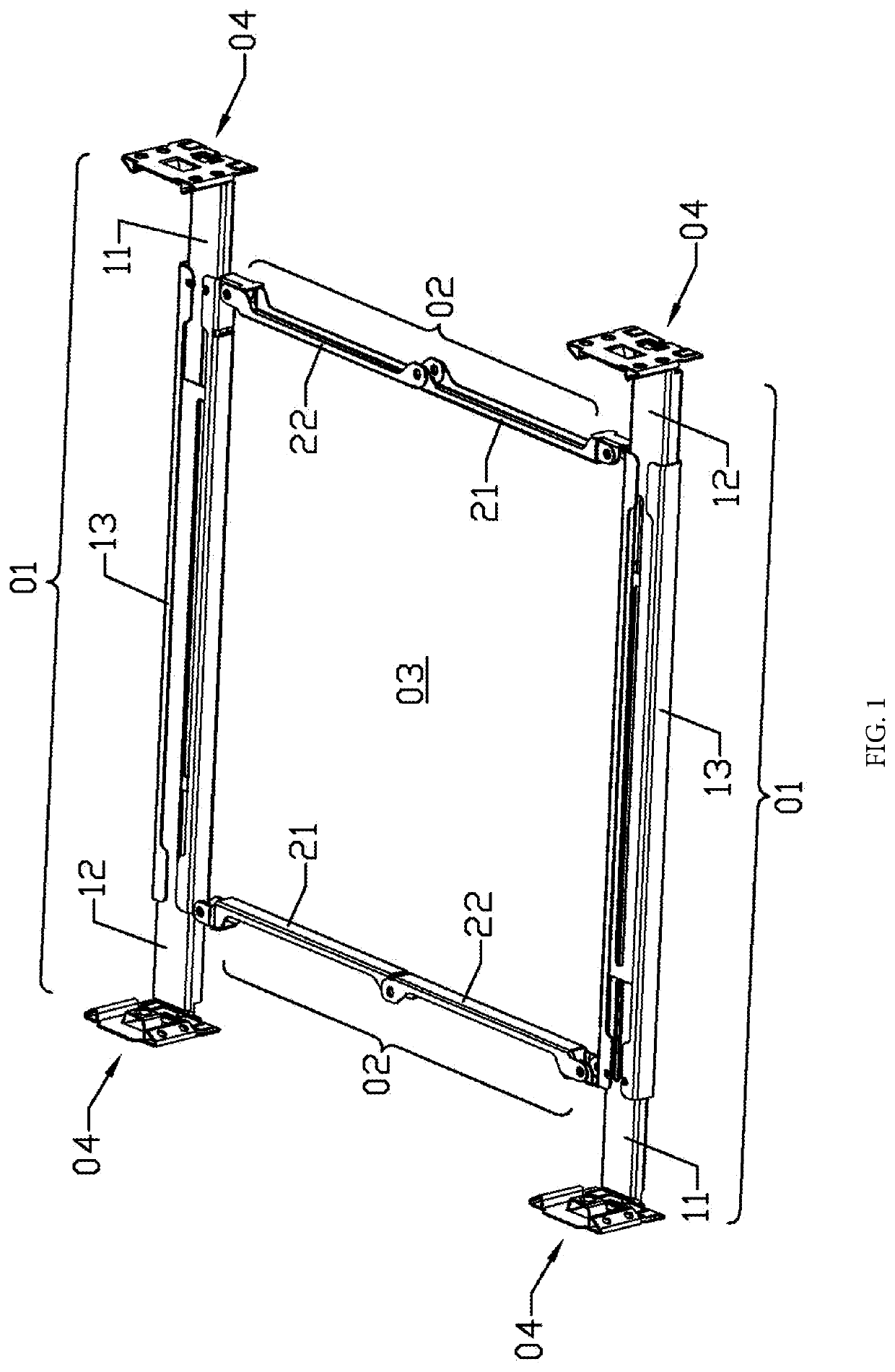
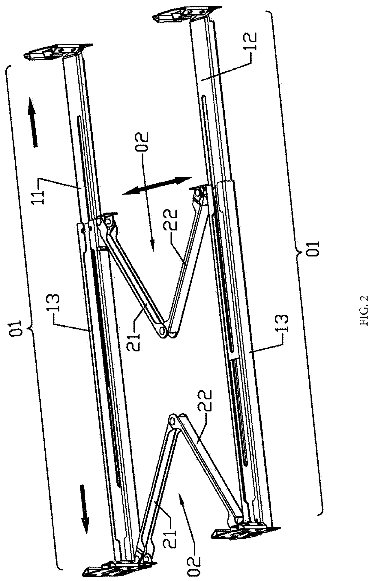
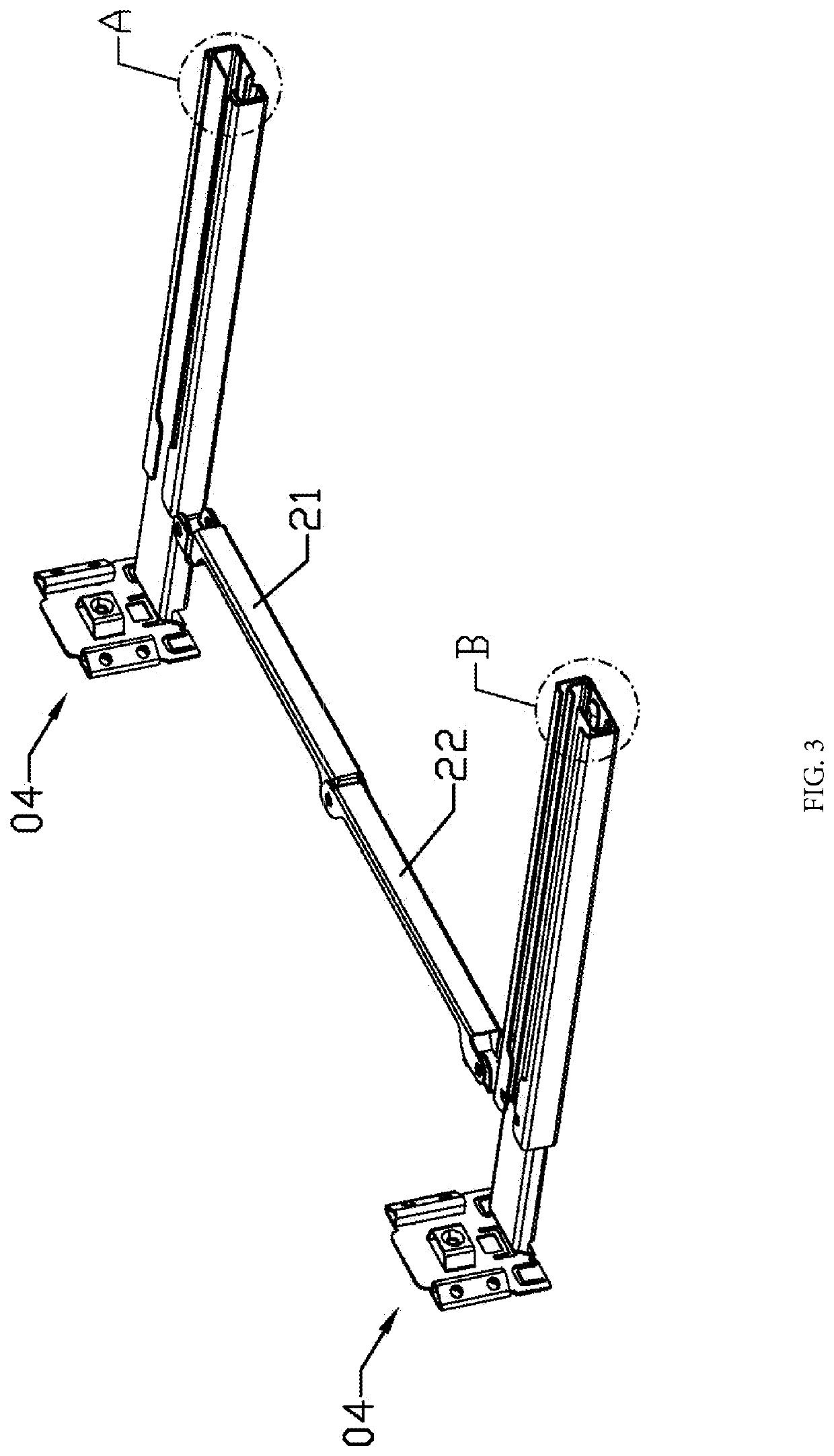
[0058]As shown in FIG. 1-3, a ventilator mounting bracket of the present invention includes two telescoping rod components 01 which can extend and shorten and two folding rod components 02 which are connected between the two telescoping rod components and are capable of being folded and unfolded. As shown in FIG. 1, the two folding rod components 02 are unfolded to stretch the two telescoping rod components such that the two telescoping rod components and the two folding rod components form a mounting hole 03; and as shown in FIG. 2, the two folding rod components 02 are folded to drive the two telescoping rod components to withdraw. Therefore, in such folded state, the outline of the ventilator mounting bracket becomes smaller such that the ventilator mounting bracket is conveniently packaged and transported and easily placed in a ceiling, and the two ends of each one of the telesco...


PUM


Abstract

The present invention discloses a ventilator mounting bracket, belonging to device installation brackets. Existing ventilator mounting brackets are smaller in adjustable distance range, difficult in installation and fixation and low in efficiency. The ventilator mounting bracket of the present invention is provided with two telescoping rod components which can extend and shorten and two folding rod components which are connected between the two telescoping rod components and can be folded and unfolded; the two folding rod components are unfolded to stretch the two telescoping rod components such that the two telescoping rod components and the two folding rod components form a mounting hole for mounting a ventilator; the two folding components are folded to withdraw the two telescoping rod components for packaging and transportation; moreover, the two ends of each one of the two telescoping rod components can be fixed at corresponding fixed parts by adjusting the length of the telescoping rod components. The mounting bracket can be conveniently and efficiently installed in new and hold houses, has a relatively large adjustable distance range, and can ensure that ventilators are installed in any position and reduce the installation time and installation cost of the ventilators.

Description

BACKGROUND OF THE INVENTION[0001]Technical Field[0002]The present invention belongs to device mounting brackets, and specifically relates to a mounting bracket for ceiling ventilators.[0003]Description of the Related Art[0004]Ventilators commercially available on the market can be mounted by many ways, and mounting brackets for ventilators vary with mounting methods. Through analysis on the usage and efficiency of existing mounting brackets, it is found that some mounting brackets have defects such as difficult installation and fixation, that some mounting brackets can be used during decoration of only new houses or can be used only after the existing ceiling opening sizes are changed during renovation of old houses, and that some mounting brackets apply to certain fixed positions or are small in adjustable distance range during installation. The flexibility of use of the mounting brackets is affected.BRIEF SUMMARY OF THE INVENTION[0005]The technical problem to be solved by and the ...

Claims


Application Information

Patent Timeline
Patent Type & Authority Patents(United States)
IPC IPC(8): F24F13/32F16M13/02F24F7/06
CPCF24F13/32F16M13/027F24F7/06F24F2221/14
Inventor GAO, SHOUYONGCHEN, JIANXU, JIANLIZHANG, KONG
Owner AUPU HOME STYLE CORP LTD
Learn More