Skin-forming apparatus and method

a technology of skin-forming apparatus and skin, which is applied in the field of skin-forming apparatus and method, can solve the problems of excessive material scraps, increased cost, and high cost of molds, and achieve the effects of reducing waste of materials, manufacturing time, cost and investmen

Active Publication Date: 2020-07-28
HYUNDAI MOTOR CO LTD +1
View PDF20 Cites 0 Cited by
  • Summary
  • Abstract
  • Description
  • Claims
  • Application Information

AI Technical Summary

Benefits of technology

[0020]The present invention has been made in an effort to solve the above-described problems associated with prior art and / or other problems, and it is an object of the present invention to provide skin-forming apparatus and method that may reduce waste of materials, manufacturing time, cost, and investment.
[0021]It is another object of the present invention to provide skin-forming apparatus and method that may improve resin flowability and formability in injection molding of a skin and prevent product defects due to generation of gas bubbles, thereby improving external quality of a product.
[0023]In another aspect, the present invention provides a skin-forming method including: injecting resin into a skin-forming space formed by a cavity of a mold; determining, using a controller, whether a temperature measured by a temperature sensor mounted in a resin flow course while being spaced apart from an inlet of a vent hole located at one side of the cavity by a predetermined distance is equal to or higher than a predetermined value while gas in the skin-forming space is discharged to an outside of the mold through the vent hole of the mold during injection of the resin; and driving, using a core driving unit, a vent core mounted in the mold to close the inlet of the vent hole to prevent leakage of the resin through the vent hole, if the temperature measured by the temperature sensor is equal to or higher than the predetermined value.

Problems solved by technology

When the PSM method is used, however, a powdering process for processing material pellets, such as TPU pellets, into powder is needed, thereby increasing the cost.
In addition, the mold is expensive, and excessive material scraps are generated.
In addition, excessive material scraps are generated.
When a raw resin is injected into a cavity defined between an upper mold unit and a lower mold unit to form a thin-film skin, however, flowability of the resin is not satisfactory due to residual gas in the mold.

Method used


Image

  • Skin-forming apparatus and method
  • Skin-forming apparatus and method
  • Skin-forming apparatus and method

Examples


Embodiment Construction

[0038]Hereinafter reference will now be made in detail to various embodiments of the present invention, examples of which are illustrated in the accompanying drawings and described below. While the invention will be described in conjunction with exemplary embodiments, it will be understood that present description is not intended to limit the invention to those exemplary embodiments. On the contrary, the invention is intended to cover not only the exemplary embodiments, but also various alternatives, modifications, equivalents and other embodiments, which may be included within the spirit and scope of the invention as defined by the appended claims.

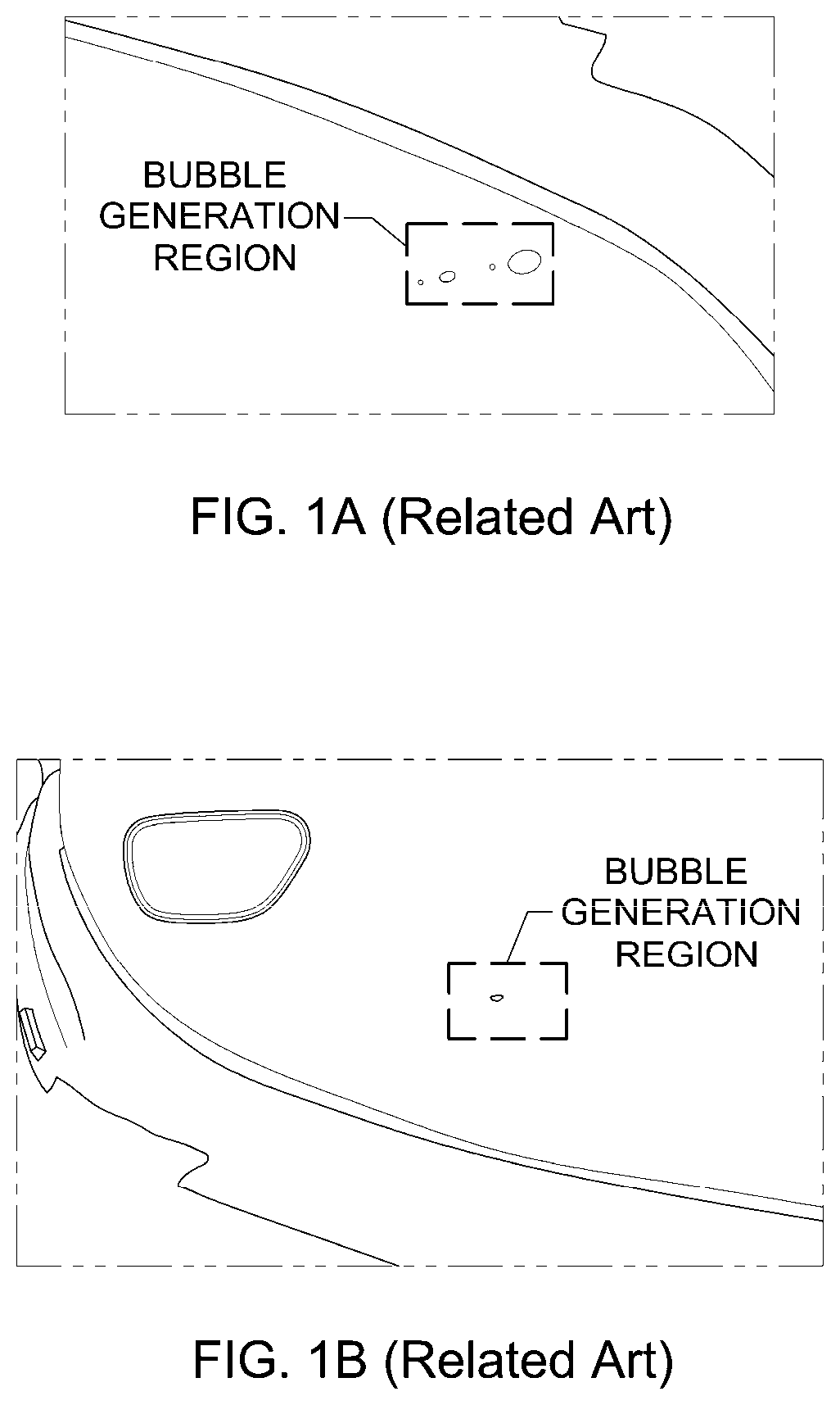
[0039]The present invention may be applied to the manufacture of a skin of a vehicle interior member. In particular, the present invention may be usefully applied to the manufacture of a skin of a crash pad through injection molding.

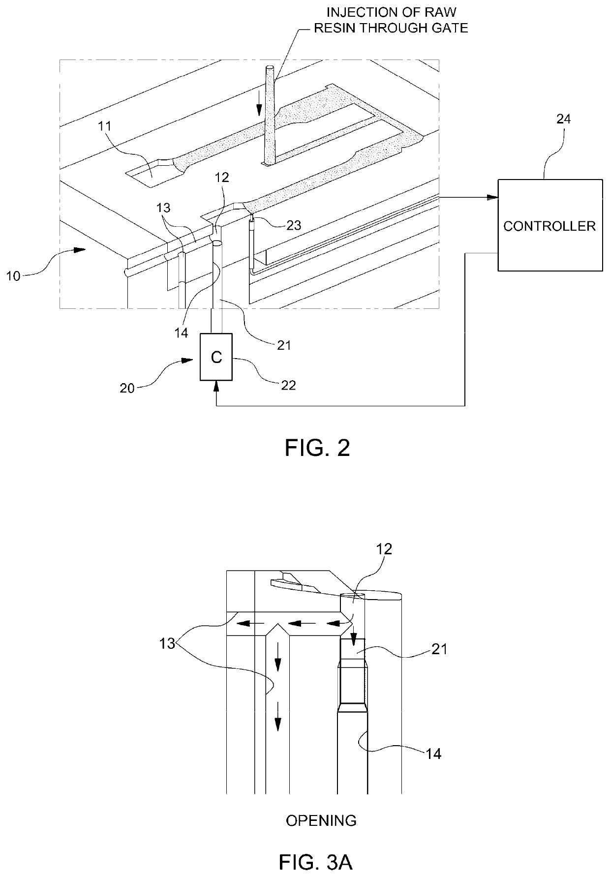
[0040]FIG. 2 is a perspective view, in section, illustrating a mold device for injection molding of a skin ...


PUM

PropertyMeasurementUnit
thicknessaaaaaaaaaa
distanceaaaaaaaaaa
temperatureaaaaaaaaaa

Abstract

Provided are skin-forming apparatus and method. The apparatus includes a mold having a cavity defining a skin-forming space and a vent core system coupled to the mold for discharging residual gas. The vent core system includes a vent hole formed in the mold and connecting the cavity of the mold to the outside, a vent core mounted in the mold for opening an inlet of the vent hole to discharge the residual gas or closing the inlet of the vent hole to block leakage of the resin, a temperature sensor disposed in a resin flow course in the cavity while being spaced apart from the inlet of the vent hole by a predetermined distance, a controller, and a core driving unit for driving the vent core to perform opening and closing operations based on the control signal of the controller in accordance with the temperature measured by the temperature sensor.

Description

CROSS-REFERENCE TO RELATED APPLICATION[0001]The present application claims priority of Korean Patent Application Number 10-2015-0078421 filed Jun. 3, 2015, the entire contents of which application are incorporated herein for all purposes by this reference.BACKGROUND[0002]Technical Field[0003]The present disclosure relates to skin-forming apparatus and method. More particularly, it relates to skin-forming apparatus and method that improve resin flowability and formability in injection molding of a skin and prevent product defects due to generation of gas bubbles, thereby improving external quality of a product.[0004]Background Art[0005]Generally, various conveniences and safety structures for a pleasant and comfortable indoor environment are mounted in a vehicle. Particularly, a crash pad is mounted in front of a driver's seat and the front passenger's seat as an indoor interior member that protects drivers and passengers when a vehicle crash occurs.[0006]A general crash pad is manuf...

Claims


Application Information

Patent Timeline
Patent Type & Authority Patents(United States)
IPC IPC(8): B29C45/34B29C45/76B29K105/04
CPCB29C45/34B29C45/76B29K2105/043B29C2945/7626B29C2945/7604B29C2945/76652B29C45/0025B29C45/80B29C2945/76732B29C2945/76859B29C2945/76494
Inventor AHN, GYE YOUNG
Owner HYUNDAI MOTOR CO LTD
Why Eureka
Try Eureka