Sealing arrangement on combustor to turbine interface in a gas turbine

a technology of sealing arrangement and combustor, which is applied in the direction of engine cooling apparatus, combustion process, lighting and heating apparatus, etc., can solve the problems of high leakage, and achieve the effects of simple design, high pressure, and high leakage ra

Active Publication Date: 2020-08-25
ANSALDO ENERGIA SWITZERLAND AG
View PDF9 Cites 0 Cited by
  • Summary
  • Abstract
  • Description
  • Claims
  • Application Information

AI Technical Summary

Benefits of technology

[0011]Accordingly, an object of the present invention is to provide a sealing arrangement on combustor to turbine interface in a gas turbine, in particular on the inner diameter between the combustor outlet and the first turbine vane, that is safe, accurate, having a simple design and suitable to allow higher pressure at the first vane.
[0012]Therefore, an object of the invention is to seal the interface between the combustor and the first turbine vane in order to reduce the leakage to a minimum also in case of axial and radial interface movements.
[0020]Advantageously, the flat dogbone seal arranged between the bulkhead and the rotor cover support reduces the leakage and, moreover, compensates the relative movements in axial direction of the combustor to turbine interface, for instance generated during a forced cooling operation.
[0024]Advantageously, this curved dogbone seal reduces the leakage and, moreover, compensates the relative movements in radial direction of the combustor to turbine interface, for instance generated during a cold start operation.
[0028]Advantageously, the above near wall cooling passage avoids the hot gas ingestion.
[0030]Advantageously, the segmented dogbone seals improve the ability to dis-assembly each single vane in case of a replacement reducing the operating cost.

Problems solved by technology

In particular, the circumferential pattern of the combustor outlet in combination with high vane movement is today a challenge for sealing solutions.
The above honeycomb sealing arrangement involves some possible risks as a full seal loss during operation or a seal delamination that can lead to high leakages.

Method used


Image

  • Sealing arrangement on combustor to turbine interface in a gas turbine
  • Sealing arrangement on combustor to turbine interface in a gas turbine
  • Sealing arrangement on combustor to turbine interface in a gas turbine

Examples


first embodiment

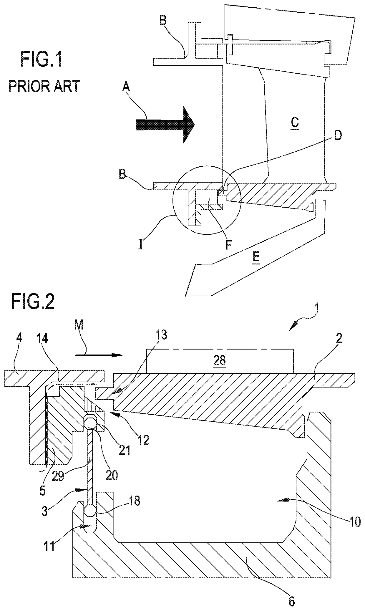
[0061]Reference is now made to FIG. 2 that is a schematic sectional view of portion of a gas turbine unit. The gas turbine unit comprises a combustor, that may be a can combustor, a turbine and a sealing arrangement 1 according to the invention at an interface between the combustor and the turbine (combustor to turbine interface 1). In particular, FIG. 2 shows an inner portion of a downstream end of a combustor liner 4 and a vane inner platform 2 of a stator vane 28 of a first turbine stage.

[0062]The vane inner platform may be a single ring along 360° about the turbine axis common to all vanes or each vane may be provided with relevant platform segment.

[0063]The main flow M defines the hot gas flow that flows from the combustor toward the first vane 28.

[0064]The expression “inner or inwardly” refer to elements or portions near to the gas turbine axis.

[0065]Facing the inner end of the sequential liner 4, the gas turbine is provided with the first turbine vane that in FIG. 2 is shown ...

second embodiment

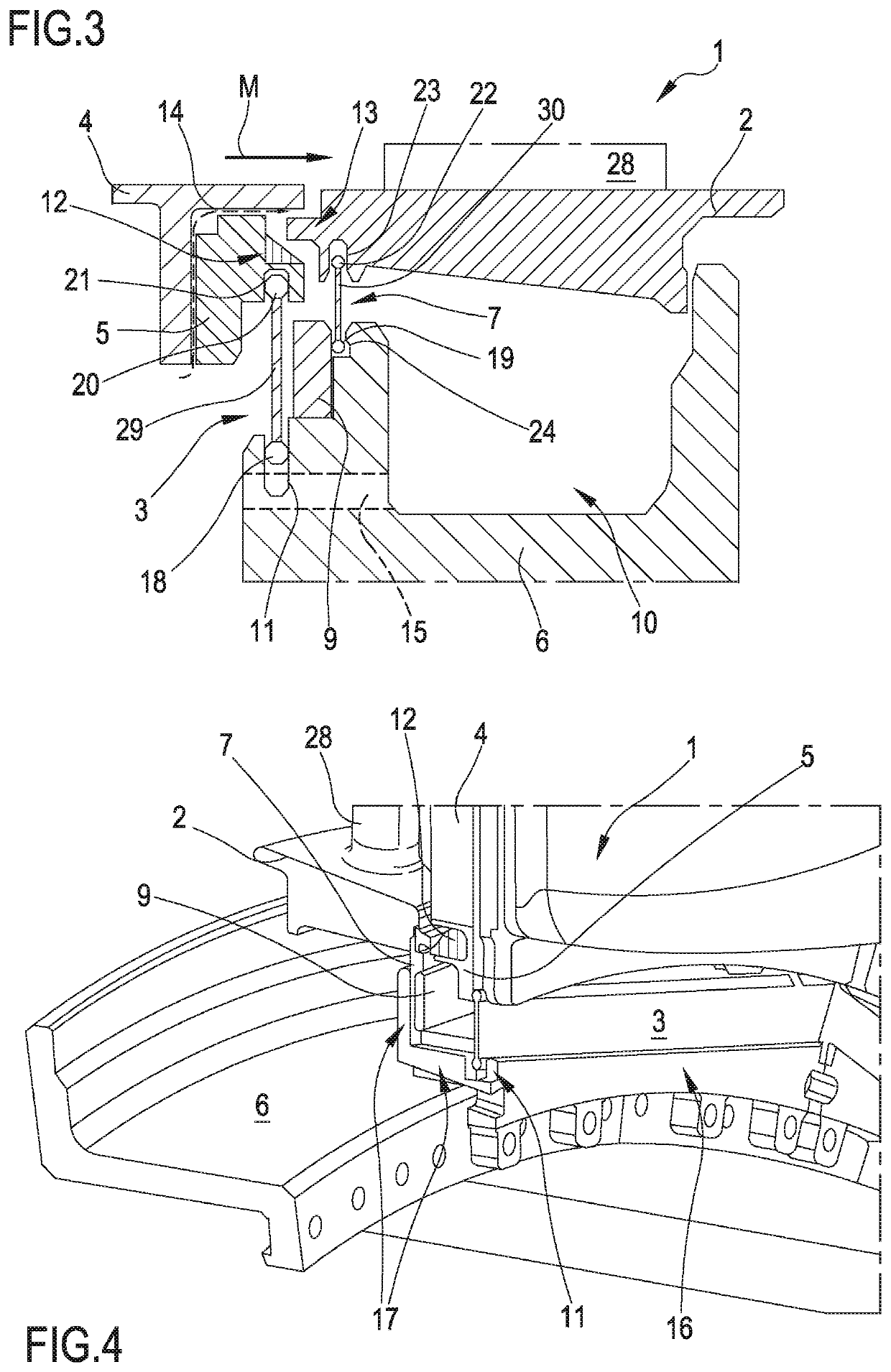
[0073]Reference is made to FIGS. 3 and 4 that are respectively a schematic sectional view and a partial perspective schematic view of a sealing arrangement according to the invention.

[0074]The vane platform 2 comprises a vane tooth 13 facing a portion of the bulkhead 5 provided with a diagonal honeycomb seal 12. Between the vane tooth 13 and the diagonal honeycomb seal 12 a gap is present.

[0075]A wall cooling passage 14 is defined between the bulkhead 5 and the sequential liner end 4.

[0076]According to this second embodiment of the invention, the gas turbine interface 1 also comprises a second dogbone seal 7 extending between the rotor cover support 6 and the inner portion of the vane inner platform 2, in addition to the flat dogbone seal 3.

[0077]This second dogbone seal 7 comprises a middle thin laminar portion (which in the embodiment of FIG. 3 is perpendicular to rotor axis with a vertical development) and two opposite bulged edges 1922. The first inner edge 19 is coupled to the ...


PUM


Abstract

A gas turbine unit having a combustor having a liner, a turbine, arranged downstream of the liner along a main flow gas direction and including a plurality of first stage vanes, a rotor cover support located inwardly of the vanes, and a sealing arrangement at a combustor to turbine interface, wherein the sealing arrangement includes a first dogbone seal extending between the rotor cover support and an inner downstream end of the liner or between the rotor cover support and a bulkhead located at the inner downstream end of the liner.

Description

PRIORITY CLAIM[0001]This application claims priority from European Patent Application No. 16179824.4 filed on Jul. 15, 2016, the disclosure of which is incorporated by reference.FIELD OF THE INVENTION[0002]The present invention relates to a gas turbine unit comprising at least a combustor and at least a turbine along a main flow gas direction.[0003]In particular, the present invention relates to a sealing arrangement located between the combustor outlet and the turbine inlet.[0004]More in particular, the present invention relates to a sealing arrangement located on the inner diameter of the combustor to turbine interface in a gas turbine.[0005]Moreover, the present invention relates to a method for installing the above sealing arrangement.DESCRIPTION OF PRIOR ART[0006]In a gas turbine, seals are used for sealing between static components of a turbine respective at the interfaces of turbine components. For example, seals are used for sealing cooling-air paths, for sealing between the...

Claims


Application Information

Patent Timeline
Patent Type & Authority Patents(United States)
IPC IPC(8): F01D9/02F01D11/06F23R3/60F01D3/04F01D11/00F16J15/00F02C7/20F02C7/18
CPCF16J15/00F01D3/04F23R3/60F01D11/001F01D11/005F01D9/023F01D11/06F02C7/185F02C7/20
Inventor IMFELD, JOSTMATHEWS, HANS-CHRISTIANBENZ, URS
Owner ANSALDO ENERGIA SWITZERLAND AG
Why Eureka
Try Eureka