Shock absorber with comfort valve

a technology of shock absorber and comfort valve, which is applied in the direction of shock absorbers, mechanical equipment, transportation and packaging, etc., can solve the problems of not being very comfortable, affecting the comfort of users, and the movement behavior of vehicles being damaged,

Active Publication Date: 2020-09-01
KONI BV
View PDF17 Cites 0 Cited by
  • Summary
  • Abstract
  • Description
  • Claims
  • Application Information

AI Technical Summary

Benefits of technology

[0008]It is an objective of the invention to provide a shock absorber (damper) providing a damping characteristic that is conceived as comfortable.
[0009]It is another or alternative objective of the invention to provide a shock absorber having a simple and straightforward design.
[0010]It is yet another or alternative objective of the invention to provide a shock absorber providing a standard piston design with a big range of characteristic requirements with flexible cost friendly implementation.
[0011]It is yet another or alternative objective of the invention to provide improved ride behaviour with only minor changes at low cost to available damper designs.
[0012]It is yet another or alternative objective of the invention to provide a damper with many tuning abilities, especially at much lower cost.
[0043]In an embodiment the first central member channel is in direct fluid connection with the part of the first main channel in the first central member, optionally a first auxiliary channel being provided in the first central member, which extends from the first central member channel to a side of the first central member opposing the side comprising the first central member channel, to provide for a direct fluid connection between the first central member channel and the part of the first main channel in the first central member. A direct fluid connection is intended to be understood as a fluid connection in which fluid can freely flow without obstruction by a valve.

Problems solved by technology

This causes a damping behavior of movements of the vehicle that can be considered as being uncomfortable for persons in the vehicle since it sets in very abrupt.
Especially when a shock absorber is designed to provide a stiff damping characteristic it is conceived as not being very comfortable.
The construction of the shock absorber is also very complex and requires careful tuning of the various components, especially in relation to one another to achieve the required damping behavior.
However, the construction is such the frequency-sensitivity is quite badly defined.
Large-amplitude damping will set in very abruptly and not provide a comfortable driving experience.

Method used


Image

  • Shock absorber with comfort valve
  • Shock absorber with comfort valve
  • Shock absorber with comfort valve

Examples


first embodiment

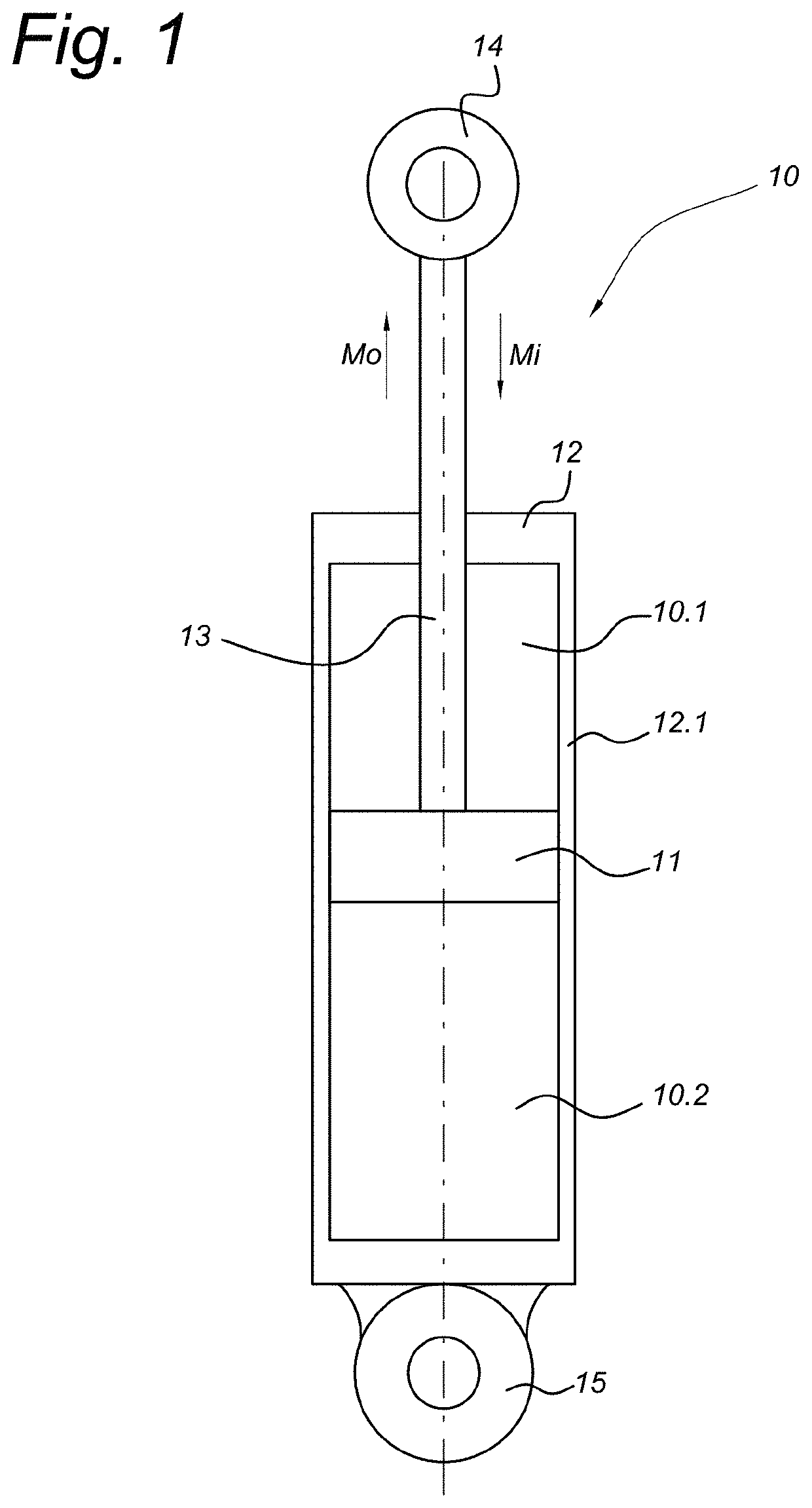
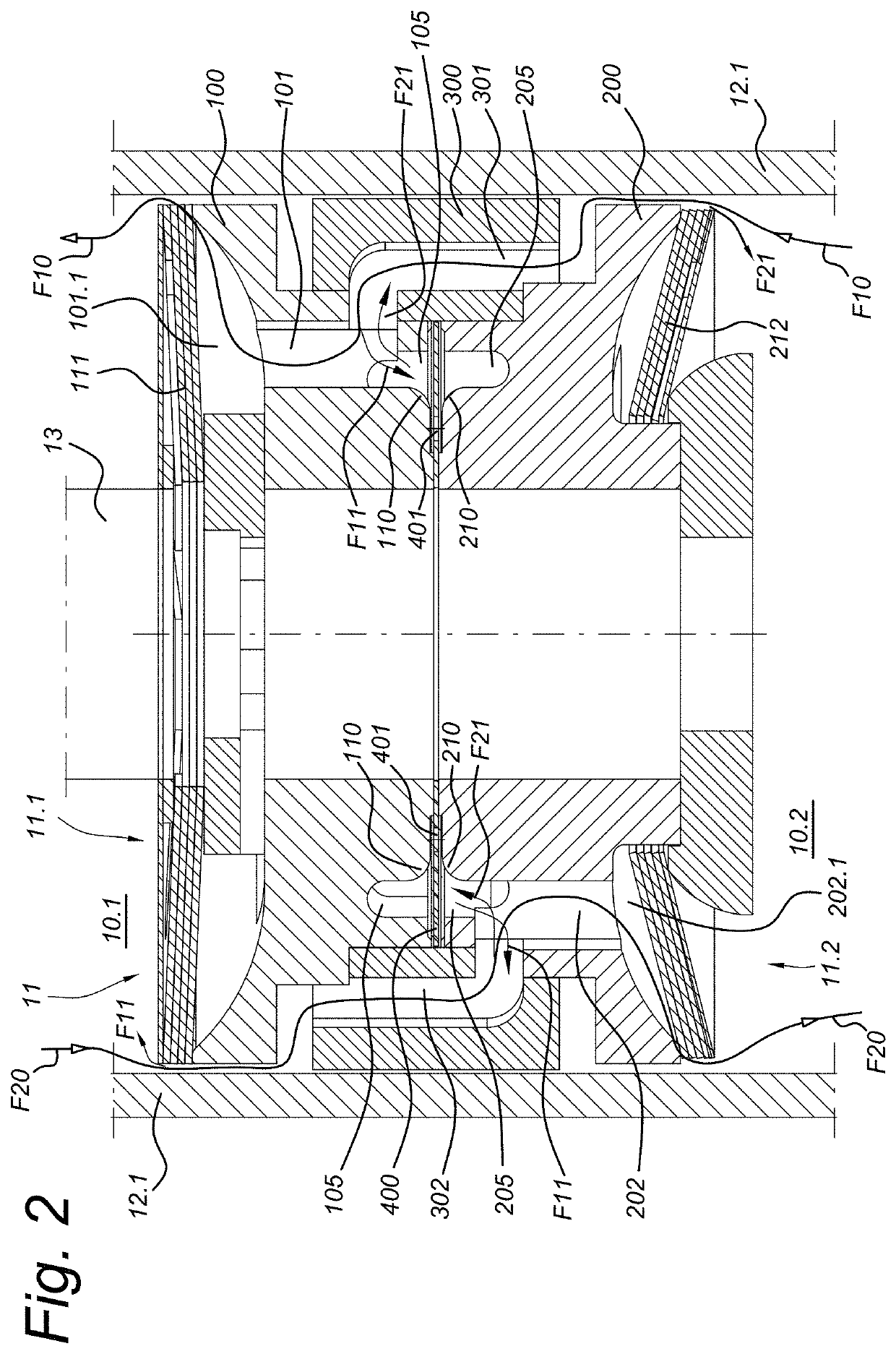
[0072]The piston is shown in more detail and in cross-section in FIG. 2. A top or first side 11.1 of the piston is directed towards and associated with the first cylinder chamber 10.1, and a bottom or second side 11.2 of the piston is directed towards and associated with the second cylinder chamber 10.2.

[0073]A first main channel 301, 101 passes through the piston 11 to allow for a first main fluid flow F10 from the second side 11.2 to the first side 11.1 of the piston and therefore from the second cylinder chamber 10.2 to the first cylinder chamber 10.1. A first main non-return valve 111 is arranged at the piston first side 11.1 and is associated with the first main channel 301, 101 so as to open for fluid flow from the second cylinder chamber 10.2 through the first main channel towards the first cylinder chamber 10.1 and piston first side 11.1. The first main non-return valve 111 is closed for fluid flow in the opposite direction, although may allow for a small constant fluid flo...

second embodiment

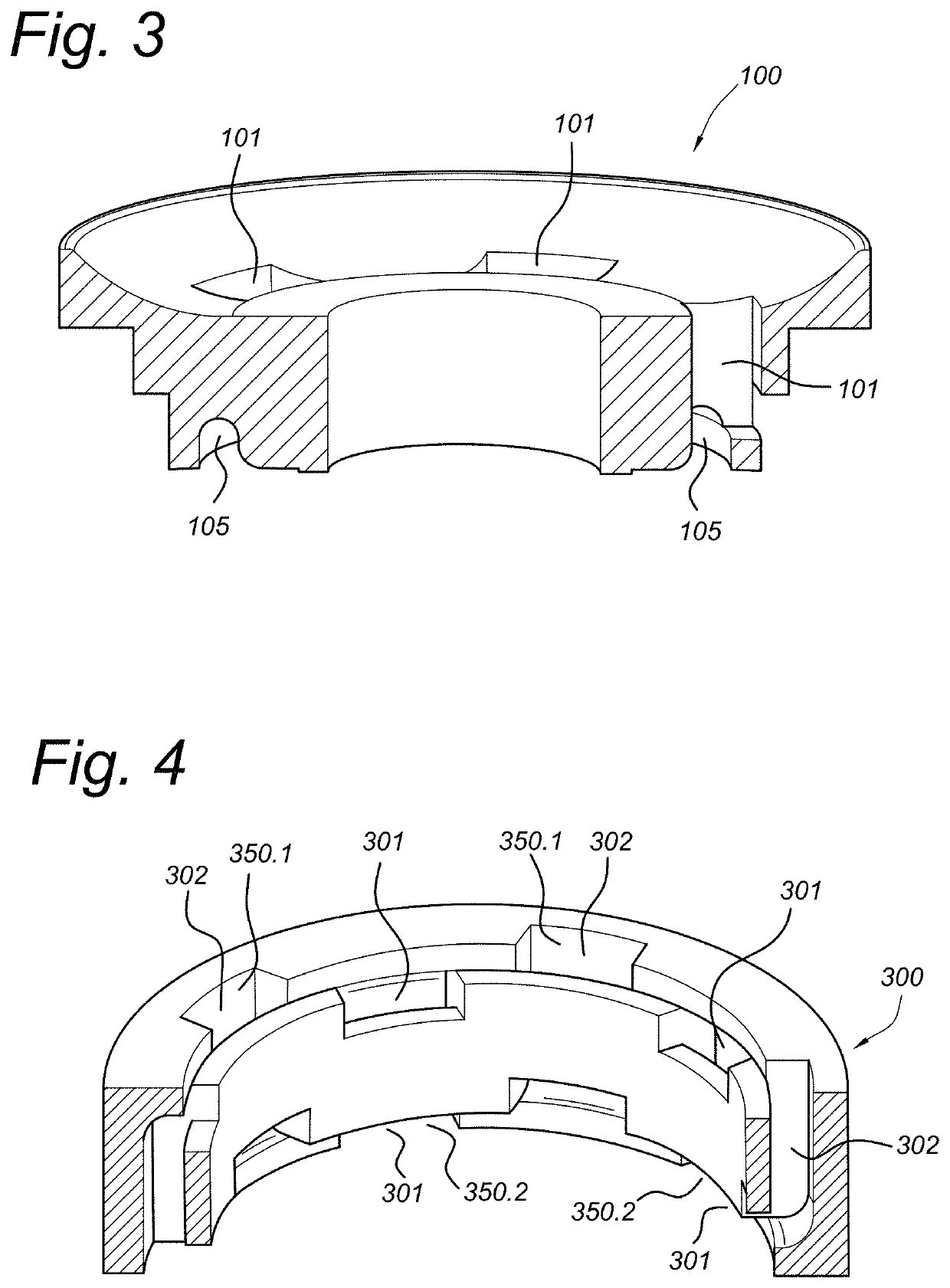
[0083]An auxiliary valve 400 in the form of an annular plate valve is provided in between the first and second central members 100, 200 in the second embodiment and its variant, such that fluid may flow past auxiliary valve 400 in a neutral or rest position thereof. The neutral position of the auxiliary valve is shown in FIGS. 2 and 6. The annular plate valve 400 is clamped at its internal perimeter between first and second central members 100, 200. The external perimeter of auxiliary annular plate valve 400 is left free to move between the first and second central members. The auxiliary annular plate valve 400 is further provided with openings 401 to allow passage of fluid from first annular central member groove 105 to second annular central member groove 205, or vice versa. FIGS. 9a and 9b show top views on two embodiments of an annular plate valve 400. The embodiment of FIG. 9a has multiple round openings 401, while the embodiment of FIG. 9b has elongated openings. Various other...


PUM


Abstract

A shock absorber includes a cylinder; a piston dividing the cylinder into first and second chambers, the piston being movable within the cylinder in inward and outward directions; a first main channel and a first main non-return valve allowing a first main fluid flow from the second to the first cylinder chamber; a second main channel and a second main non-return valve allowing a second main fluid flow from the first to the second cylinder chamber; a comfort channel allowing an auxiliary fluid flow between the first and second cylinder chambers; and a comfort valve providing an open connection for the auxiliary fluid flow through the comfort channel in a rest position of the comfort valve and closing off the auxiliary fluid flow at increasing pressure difference across the comfort valve at either inward or outward movement to influence an auxiliary fluid flow between first and second piston sides.

Description

CROSS-REFERENCE TO RELATED APPLICATIONS[0001]The present application is the U.S. National Stage filing under 35 U.S.C. § 371 of International Patent Application No. PCT / EP2016 / 079051, filed on Nov. 28, 2016, which in turn claims priority under Patent Cooperation Treaty Article 8 and / or 35 U.S.C. 119(a) to Netherlands Patent Application No. 2015875, filed on Nov. 27, 2015.FIELD OF THE INVENTION[0002]The invention relates to a shock absorber comprising a cylinder having a cylinder wall; and a piston sealing against the cylinder wall and dividing the cylinder in first and second chambers, the piston being movable within the cylinder along the cylinder wall in inward and outward directions upon inward and outward movement, respectively, of the piston inside the cylinder, a first side of the piston being associated with the first cylinder chamber and a second side of the piston being associated with the second cylinder chamber; a first main channel and a first main non-return valve assoc...

Claims


Application Information

Patent Timeline
Patent Type & Authority Patents(United States)
IPC IPC(8): F16F9/50B60G13/06F16F9/16F16F9/34F16F9/512F16F9/348
CPCF16F9/5126F16F9/3488F16F9/3482F16F9/16F16F9/3485B60G2202/24B60G13/06
Inventor DE KOCK, PAUL
Owner KONI BV
Why Eureka
Try Eureka