System and method for securing a rotor to a motor drive shaft using cam fasteners

Active Publication Date: 2009-02-03
NIDEC MOTOR CORP
View PDF5 Cites 0 Cited by
  • Summary
  • Abstract
  • Description
  • Claims
  • Application Information

AI Technical Summary

Benefits of technology

[0012]There are several advantages to this method. First, it is very simple. Manufacturing costs remain low in that the rotor itself has a very simple, straightforward design and conventional cam screws may be used. Second, the rotor can maintain a very narrow profile because the head portion of the cam screws may fit within a counter bore portion of the bores. Third, the cam screws for clamping the rotor to the rotor shaft are always accessible even after the stator housing is mounted. Fourth, for a given outer diameter, larger motor shaft sizes can be accommodated than those using the slotted spoke option. Fifth, this mounting system achieves clamping forces equal to or greater than that of set screw techniques, greater then those of the spoke style, and more consistent and less prone to failure than the split ring with tapered hub method.

Problems solved by technology

However, there are disadvantages with each of these current systems.
However, there are several disadvantages with this rotor design.
First, because the magnetic encoder rotor is located inside the stator housing, the side edge of the rotor is inaccessible after mounting the stator housing.
A rotor cannot be repositioned, repaired, or replaced without removing the stator housing.
Second, it is more difficult to reliably achieve maximum clamping force with set screw tightening tools.
For example, it is more expensive to manufacture than using simple set screws.
Further, the clamping forces are inferior to those of set screw methods.
Lastly, the size of motor shaft diameters that can be accommodated are limited by the fact that the space between the slotted spoke and an adjacent spoke must be wide enough for a wrench or other tightening tool to fit.
As with other designs, this system for mounting rotor on a motor shaft is more expensive than a set screw system.
However, this system is subject to assembly errors.
If the clamping screws are not tightened uniformly (or if the screw over the split in the split ring) is tightened first, the clamping force is severely limited.
There may be no immediate external indication of improper clamping, but such an improperly clamped rotor will slip during normal operation and cause system failures.

Method used


Image

  • System and method for securing a rotor to a motor drive shaft using cam fasteners
  • System and method for securing a rotor to a motor drive shaft using cam fasteners
  • System and method for securing a rotor to a motor drive shaft using cam fasteners

Examples


Embodiment Construction

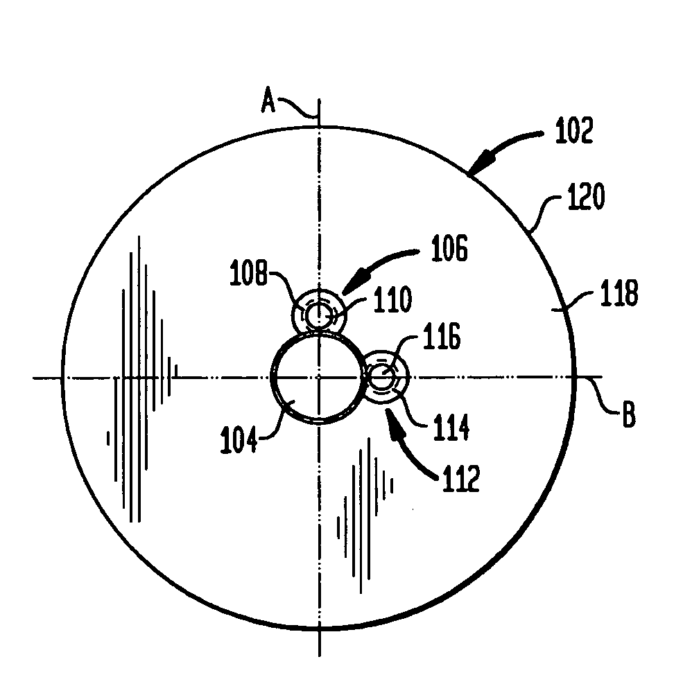
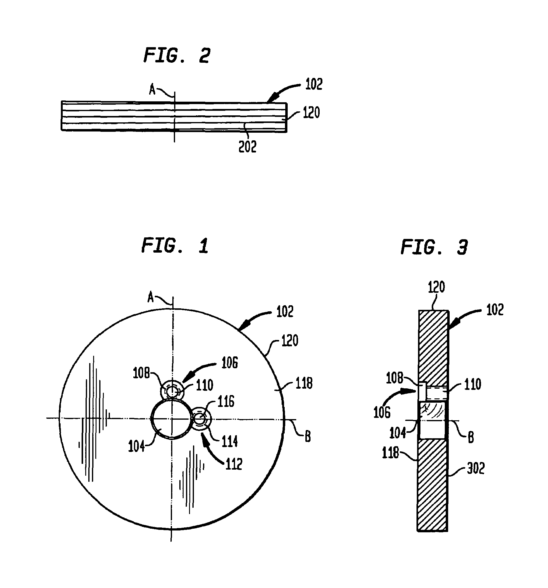
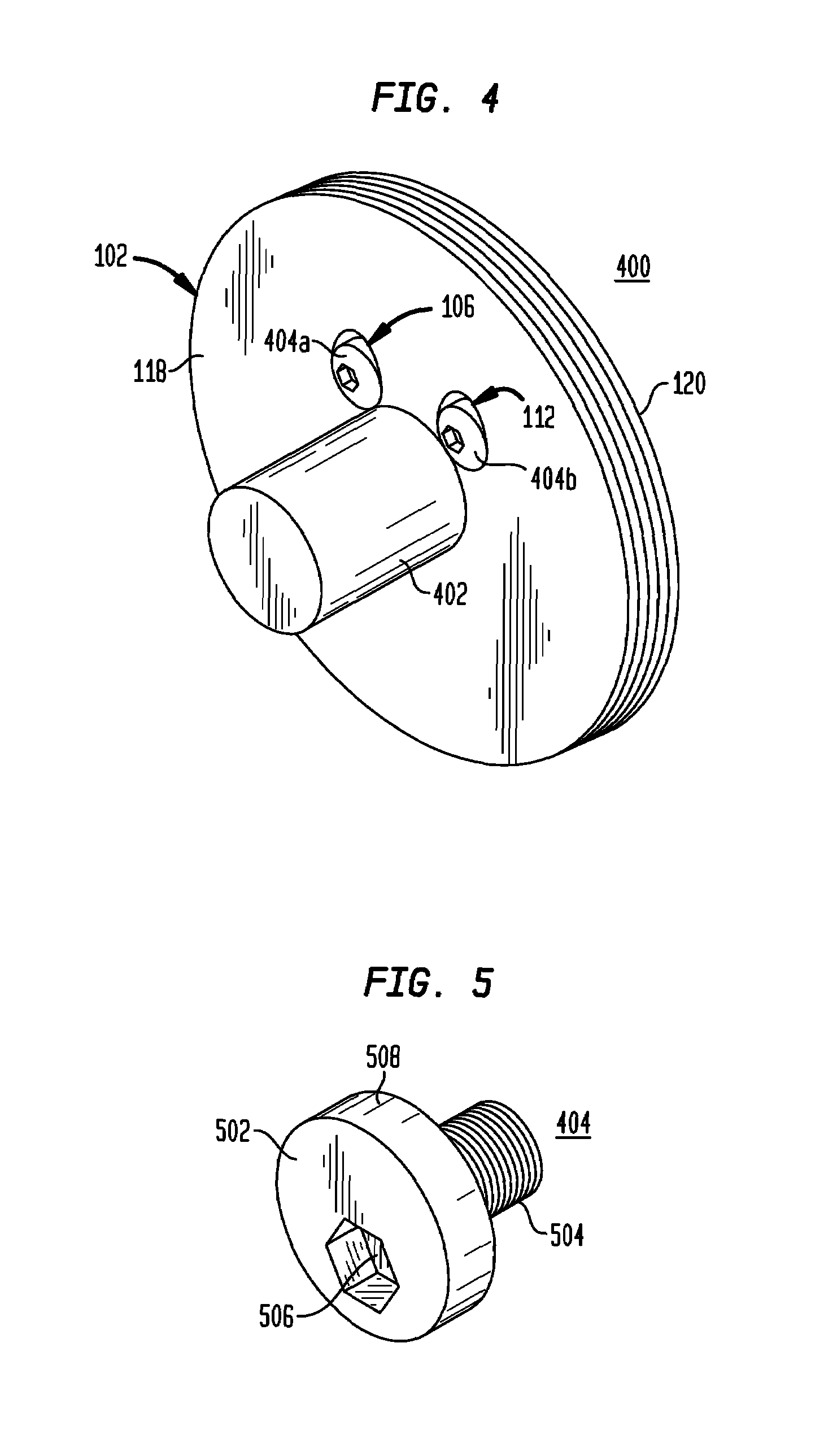
[0019]The rotor assembly of the present invention is shown in the accompanying figures. FIGS. 1-3 show the preferred embodiment of a rotor 102 having a central bore 104 positioned about the intersection of a first, vertical, axis A and a second, horizontal, axis B wherein the first axis A is perpendicular to the second axis B. This central bore 104 has a diameter slightly larger than the diameter of the motor shaft. The rotor 102 has a first stepped bore 106 consisting of a tapped hole 110 through the thickness of the rotor 102 and a counterbored hole 108. The tapped hole 110 and counterbored hole 108 are to accommodate the cam screw described below. The first stepped bore 106 is positioned adjacent to and adjoining with the central bore 104 aligned with the axis A such that the counterbored hole 108 intersects with the central bore 104.

[0020]In the preferred embodiment, about one quarter of the circumference of the counterbored hole 108 intersects with the central bore 104. In addi...


PUM

PropertyMeasurementUnit
Thicknessaaaaaaaaaa
Diameteraaaaaaaaaa

Abstract

A rotor assembly for mounting a rotor to a motor shaft having a rotor with a centrally positioned central bore, the diameter of which is slightly larger than a diameter of the motor shaft, a first stepped bore intersecting the central bore and being aligned along a first axis of the rotor, and a second stepped bore also intersecting the central bore and being aligned along a second axis of the rotor. A first cam fastener is disposed within the first stepped bore, and a second cam fastener is disposed within the second stepped bore. Upon rotating the first and second cam fasteners, they engage the motor shaft thereby securely clamping the rotor to the motor shaft.

Description

BACKGROUND OF THE INVENTION[0001]1. Technical Field[0002]The present invention relates to rotors, and in particular, to a magnetic encoded rotor incorporating a means for securing the rotor to a motor drive shaft, the means incorporating one or more cam-type fasteners.[0003]2. Related Art[0004]There are various systems and methods for mounting modular magnetic encoder rotors to a motor drive shaft (or motor shaft). However, there are disadvantages with each of these current systems.[0005]A first system is directed to a rotor having an external hub encircling and extending away from the central aperture. The external hub typically has a diameter less than the outer diameter of the rotor and extends from the face of the hub a relatively short distance. A plurality of set screws is inserted through holes in the hub to engage the motor shaft. Upon tightening, the set screws secure the rotor to the motor shaft. In this embodiment, the external hub is typically positioned external to a st...

Claims


Application Information

Patent Timeline
IPC IPC(8): H02K1/06
CPCH02K1/28Y10T403/7024Y10T29/49963Y10T403/7051Y10T29/49012
Inventor KRAMER, KENNETH M.
Owner NIDEC MOTOR CORP
Why Eureka
Try Eureka