
Systems and methods for dynamic building evacuation

a dynamic and building technology, applied in the field of building safety systems and methods, can solve the problems of putting evacuees in greater danger, static evacuation plans that cannot be changed to reflect the realities, and fire can in theory occur anywher

Active Publication Date: 2020-09-08
KRONZ JASON +1
View PDF8 Cites 9 Cited by
  • Summary
  • Abstract
  • Description
  • Claims
  • Application Information

AI Technical Summary

Benefits of technology

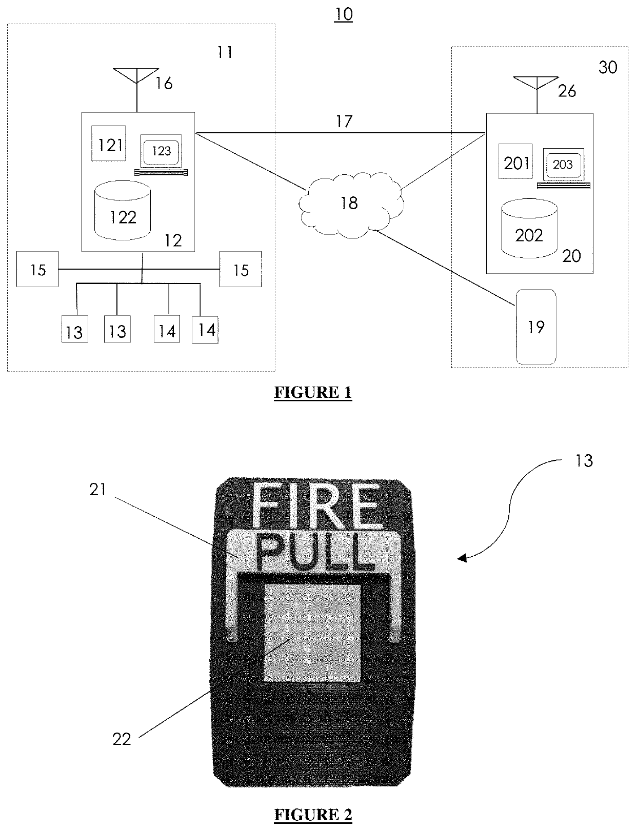
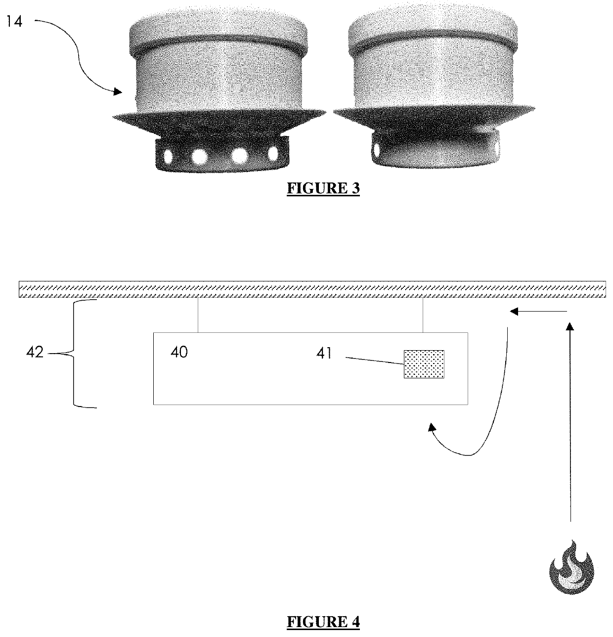
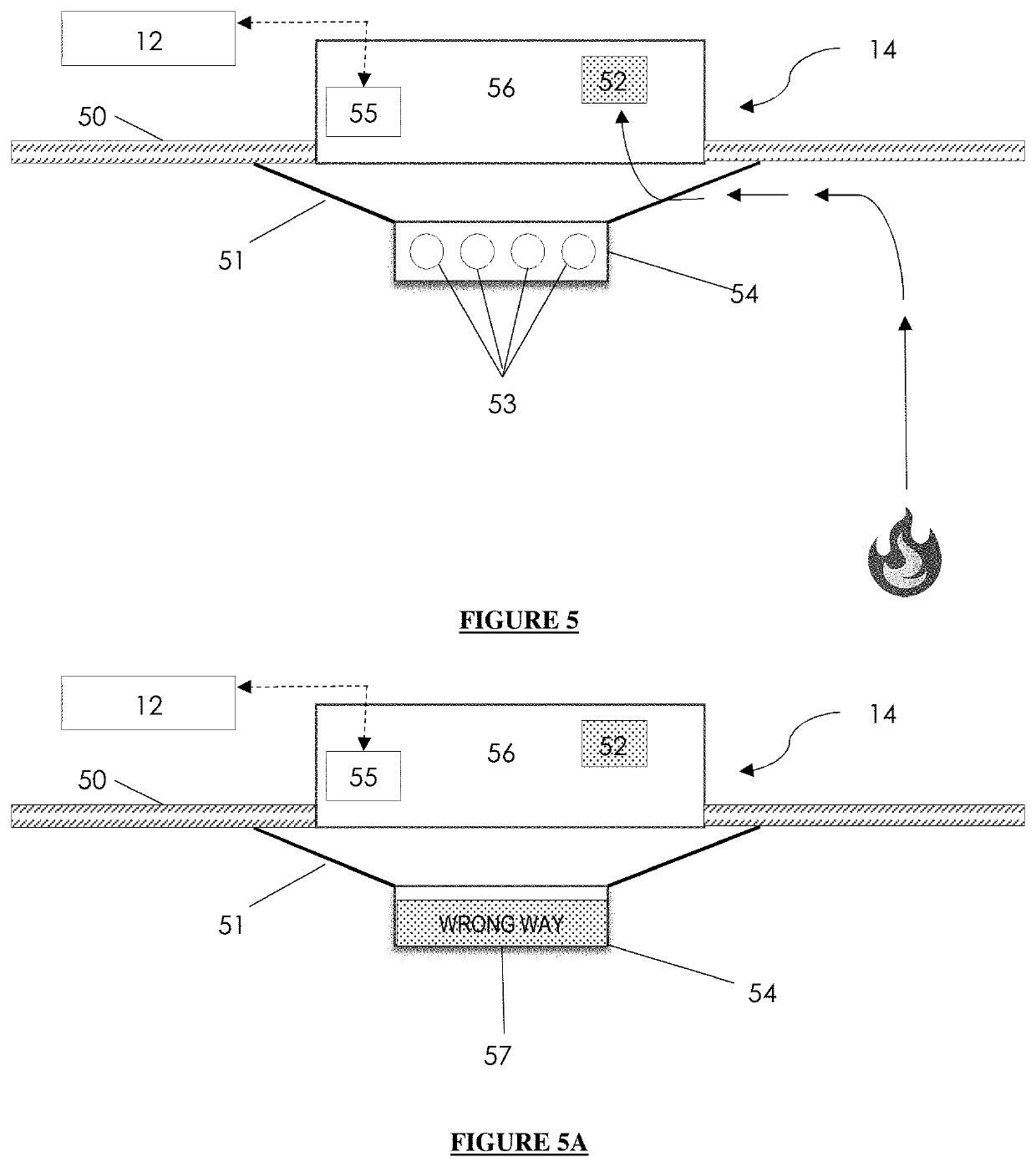
The patent describes a system that uses sensors and control units to detect and respond to emergency situations in real-time. This system can analyze existing evacuation plans and change them in real-time, providing customized evacuation routes for evacuees. The sensors and signals can include displays or signals that help people quickly understand what is happening and what to do. Overall, this system improves the efficiency and effectiveness of emergency response.

Problems solved by technology

The technical problem addressed in this patent text is the limitations of current building evacuation systems, which have static evacuation plans that cannot be changed to reflect the realities of an emergency situation. These systems usually involve evacuees proceeding directly to the nearest building exit or stairwells leading to the nearest exit, which can put them in greater danger if a fire occurs anywhere in the building. Additionally, the location of building occupants may not be accurately known, and the precise location and nature of an emergency condition may not be immediately known.

Method used


Image

  • Systems and methods for dynamic building evacuation
  • Systems and methods for dynamic building evacuation
  • Systems and methods for dynamic building evacuation

Examples


Embodiment Construction

[0020]The invention is described in preferred embodiments in the following description with reference to the Figures, in which like numbers represent the same or similar elements. Reference throughout this specification to “one embodiment”, “an embodiment”, or similar language means that particular feature, structure, or characteristic described in connection with the embodiment is included in at least one embodiment of the present invention. Thus, appearances of the phrases “in one embodiment”, “in an embodiment”, “in certain embodiments”, and similar language throughout this specification may, but do not necessarily, all refer to the same embodiment. It should be noted that, as used in this description, the singular forms “a”, “an”, and “the” include plural referents unless the context clearly dictates otherwise.

[0021]The described features, structures, or characteristics of the invention may be combined in any suitable manner in one or more embodiments. In the following descripti...


PUM


Abstract

A disclosure and claims to systems and methods for allowing rapid detection and display of an emergency condition using a plurality of specially-constructed multifunction sensors and display units, which allow building evacuation plans to be evaluated, modified, and transmitted to building occupants.

Description


Claims


Application Information

Patent Timeline
Owner KRONZ JASON
Learn More