Water collection/deflection arrangements

a technology of water collection and deflection, applied in the direction of climate sustainability, stationary conduit assembly, trickle cooler, etc., can solve the problems of increased fan energy consumption for a given airflow, poor fan performance, higher unit cost, etc., to reduce airflow resistance, improve air distribution, and improve air spray

Active Publication Date: 2020-09-15
BALTIMORE AIRCOIL CO INC
View PDF29 Cites 2 Cited by
  • Summary
  • Abstract
  • Description
  • Claims
  • Application Information

AI Technical Summary

Benefits of technology

[0002]This invention concerns evaporative cooling towers, fluid coolers and evaporative condensers, and specifically the amelioration of the air and spray water flow within the evaporative cooling equipment. This invention improves air distribution while reducing airflow resistance to increase the thermal capacity for a given footprint of the evaporative cooling tower. In addition, this invention seeks to provide self-cleaning, easy to access, inspect and maintain evaporative cooling equipment.
[0003]The improvement in airflow distribution, and decrease in airflow resistance, is achieved by reducing the amount of obstruction and turns in the airflow path, and by opening the plenum area around the fan. Typical forced draft evaporative cooling equipment with side inlet fans have uneven airflow distribution to the heat exchanger arranged above the fan. Solid baffles or fan housings are typically arranged to shield the mechanical and fan components from the falling water droplets through the heat exchanger. Given the near perpendicular arrangement of the entering air velocity provided by the fan, the turning losses to the heat exchanger significantly contribute to the total static pressure acting against the fan and increased fan energy consumption for a given airflow. For forced draft evaporative cooling equipment using an unhoused fan, the fans and fan plenum are separated from the heat exchanger for water management concerns, and are not positioned directly under the heat exchanger section, resulting in poor fan performance due to higher airflow resistance, large unit footprint and higher unit cost due to the side-by-side heat exchanger and fan sections.
[0004]In this invention, overlapping gutters water collection systems, as well as overlapping sloped panel water systems, are introduced to improve airflow distribution and decrease airflow resistance, thus increasing unit capacity.
[0005]The overlapping gutter water collection systems are designed to collect the spray water flowing from the top side, while letting air flow vertically through from the bottom side. The system is made of single-piece gutter assemblies stacked side by side and overlapping, which typically only cover part of the footprint of the unit, which allows for fine balancing of the airflow resistance and greater control of the airflow paths through the units. By covering only part of the unit footprint, and by being sloped, the water collection systems create a water cascade from the water collection channels to the sump. The cascading water is mixed with air passing through which becomes an extended rain zone, which allows for additional cooling of the spray water resulting in higher unit thermal performance. However, some designs require the complete footprint of the unit to be covered by the overlapping gutter water collection systems. One improvement of the invention presented is that the sloped overlapping water gutter collection system assemblies are composed of two water collection channels: a primary water collection channel that collects most of the spray water, and a secondary water collection channel that collects the remaining spray water. Both channels should be wide enough to prevent clogging due to debris and other factors, and to be easily inspected and cleaned, as needed. The air passages of the gutter assemblies are designed to minimize airside pressure drop while improving water collection performance. Drip edges can be added to improve water catching performance, as necessary. If water splash out is a concern, a water collection trough can be incorporated in the design, at the discharge side of the water collection channels of the gutter system. The spray water is collected in the trough, so it can drain to the sump via a pipe, under the action of gravity, reducing the amount of water splashing in the sump. In addition, louvers can be added under the water collection system to isolate the sump area from the fan area. If high water collection capacities are required, a design with three integrated water collection channels can be used. The gutter assemblies could be parallel or perpendicular to the direction of the air intake, depending on the needs of the application. In some embodiments, overlapping water gutter collection systems can also function as water silencers by catching most or some of the spray, shortening the waterfall distance from the heat exchanger to the sump.
[0006]The overlapping sloped panel water management systems are designed to allow air generated from the fan to pass between panels to the heat exchanger, and to catch water droplets falling from the heat exchanger and direct them to the sump. The air passages of the sloped panel assemblies are designed to minimize airside pressure drop while improving water collection performance. This allows for reduced airflow resistance from turning losses and airflow obstructions, reducing fan energy consumption, and improving thermal performance. For most embodiments presented, sloped panel assemblies only cover part of the footprint of the unit, which allows for fine balancing of the airflow resistance and greater control of the airflow paths through the units. By covering only part of the unit footprint, the water management systems can create a water cascade from the water collection channels to the sump. The cascading water creates an extended rain zone which allows for additional cooling of the spray water resulting in higher unit thermal performance. The water management panels could be parallel or perpendicular to the direction of the air intake, depending on the needs of the application.

Problems solved by technology

Given the near perpendicular arrangement of the entering air velocity provided by the fan, the turning losses to the heat exchanger significantly contribute to the total static pressure acting against the fan and increased fan energy consumption for a given airflow.
For forced draft evaporative cooling equipment using an unhoused fan, the fans and fan plenum are separated from the heat exchanger for water management concerns, and are not positioned directly under the heat exchanger section, resulting in poor fan performance due to higher airflow resistance, large unit footprint and higher unit cost due to the side-by-side heat exchanger and fan sections.
However, some designs require the complete footprint of the unit to be covered by the overlapping gutter water collection systems.
Finally, keeping the spray water as far away from the air intake as possible greatly reduces to risk of water splashing out through the fan, and the risk of freezing in the winter, especially when the fans are not in operation.

Method used


Image

  • Water collection/deflection arrangements
  • Water collection/deflection arrangements
  • Water collection/deflection arrangements

Examples


fifth embodiment

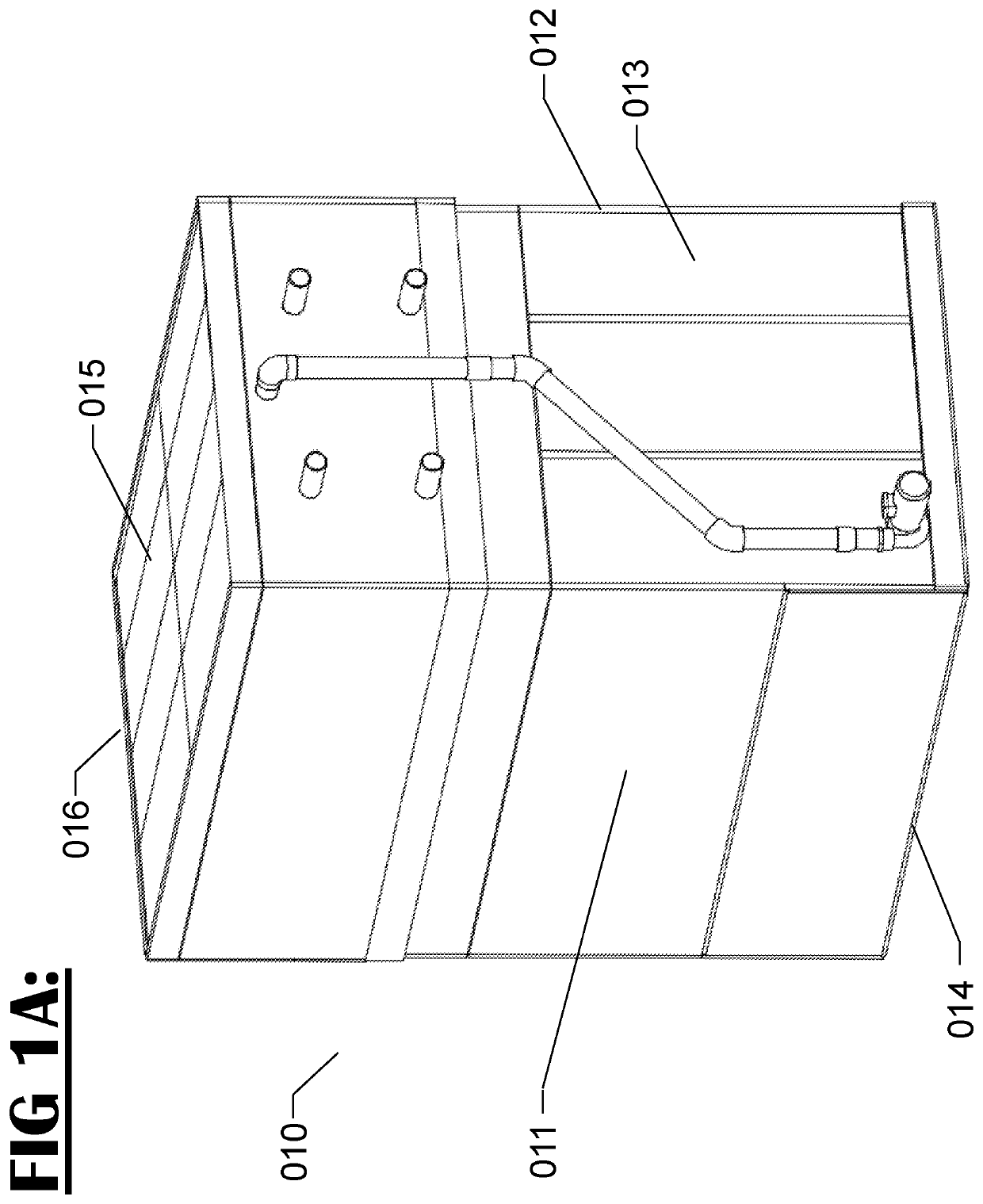
[0041]Referring now to FIGS. 4A and 4B, overlapping gutter water collection system 400 is in accordance with the present invention. FIG. 4A shows a perspective view of the overlapping gutter water collection system 400. Overlapping gutter water collection system 400 is shown to be comprised of a plurality of gutter assemblies 410, side panels 411, back panel 412, bottom support channel 413, and top support channel 414. The overlapping gutter water collection system 400 is designed to span the full distance between face 013 and face 016, as defined in FIG. 1, as shown in FIG. 2A, and is supported by the side 411 and back panels 412, along with the bottom support channel 413, which are attached to the unit structure. The gap between the side 411 and back panels 412, along with the bottom support channel 413, and the unit structure is kept water tight by gasket sealing, butyl tape, and / or coating, so that the spray water does not leak through the gap, but the sealing methodology is not...

embodiment 700

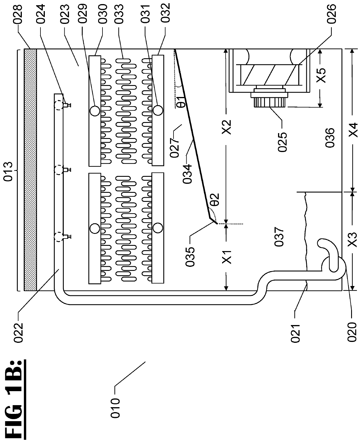
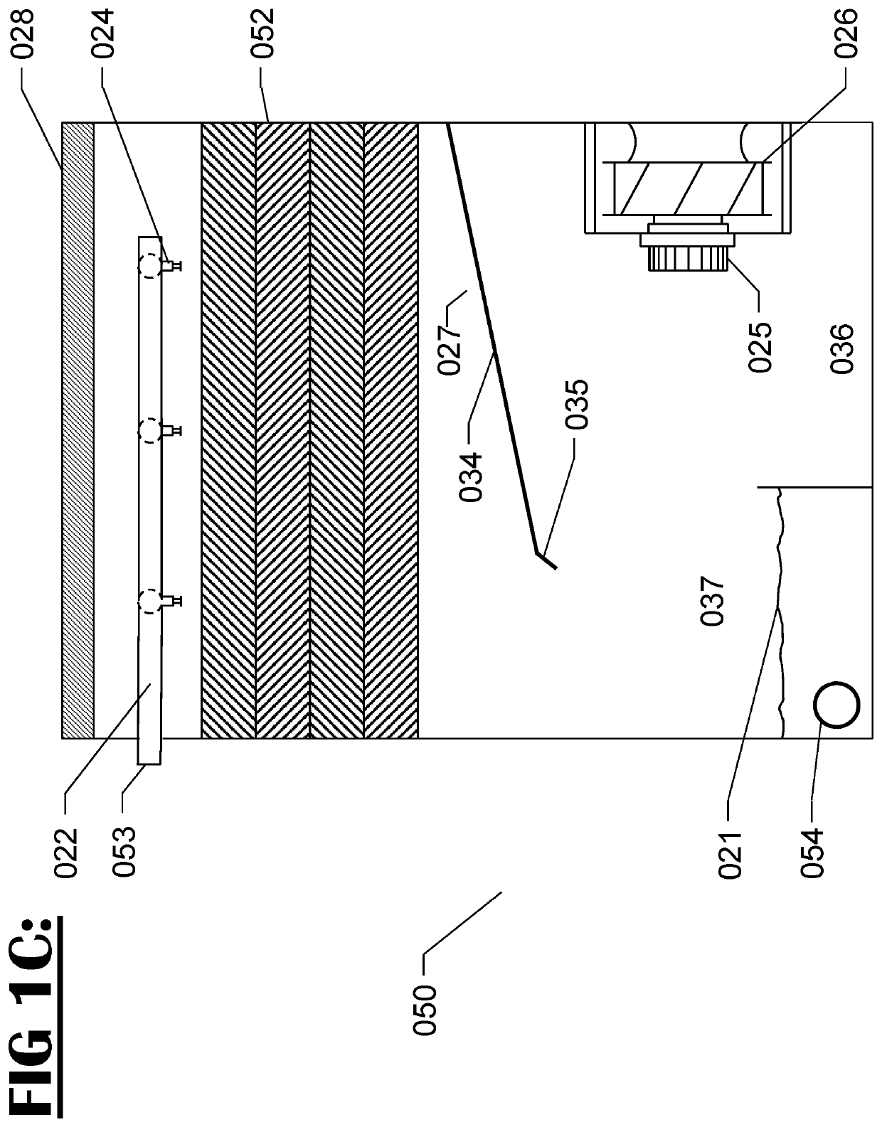
[0057]Referring now to FIG. 13A, a twenty-eight embodiment is shown. Similar components use similar numerals as FIG. 1B in FIGS. 13A and 13B. As shown in FIG. 13A, embodiment 700 is an evaporative indirect heat exchanger product which could be a closed circuit cooling tower or an evaporative condenser, with an overlapping sloped panel water management system 701, in accordance with a twenty-eight embodiment of the present invention. Each sloped panel is composed of a generally straight but sloped section 602, a generally downward pointing drip edge 603, and a generally upward pointing deflection plate 604 to prevent overflow and limit splash out. The panels of the water management system 701 are sloped towards the sides of the unit, so as to direct the water towards lateral water collection troughs 703, from which the water cascades to the sump 021. An angled deflection plate 702 forms the top part of the overlapping sloped panel water management system 701. The overlapping sloped p...


PUM


Abstract

Improved water management systems which deflect or collect evaporative liquid exiting counterflow heat exchangers and improve airflow distribution are provided. Such heat exchangers include open cooling towers, closed circuit cooling towers, and evaporative condensers. The improved water management systems eliminate water splash out and the noise associated with water splashing. Further, when the fan assemblies are located below the evaporative heat exchanger, the improved water management systems keep the fans dry and prevent freezing in subzero climates.

Description

RELATED APPLICATIONS[0001]The application claims benefit of U.S. provisional application 62 / 402,038, filed Sep. 30, 2016, the entirety of which is hereby incorporated herein by reference.BACKGROUND AND SUMMARY OF THE INVENTION[0002]This invention concerns evaporative cooling towers, fluid coolers and evaporative condensers, and specifically the amelioration of the air and spray water flow within the evaporative cooling equipment. This invention improves air distribution while reducing airflow resistance to increase the thermal capacity for a given footprint of the evaporative cooling tower. In addition, this invention seeks to provide self-cleaning, easy to access, inspect and maintain evaporative cooling equipment.[0003]The improvement in airflow distribution, and decrease in airflow resistance, is achieved by reducing the amount of obstruction and turns in the airflow path, and by opening the plenum area around the fan. Typical forced draft evaporative cooling equipment with side ...

Claims


Application Information

Patent Timeline
Patent Type & Authority Patents(United States)
IPC IPC(8): F28F25/04F28C1/00F28D5/02F28C1/14F28F25/12
CPCF28C1/00F28D5/02F28F25/04F28F25/12F28C1/14Y02B30/70
Inventor ROUSSELET, YOHANN LILIANAUTH, CHRISTOPHER PATRICKMALAMUD, DINA
Owner BALTIMORE AIRCOIL CO INC
Why Eureka
Try Eureka