Water Collection Arrangement

a technology of water collection and water collection, which is applied in the direction of trickle coolers, stationary conduit assemblies, lighting and heating apparatus, etc., can solve the problems of increased fan energy consumption for a given airflow, poor fan performance, and higher unit cost, so as to improve air and spray water flow, improve air distribution, and reduce airflow resistance

Active Publication Date: 2019-02-28
BALTIMORE AIRCOIL CO INC
View PDF0 Cites 1 Cited by
  • Summary
  • Abstract
  • Description
  • Claims
  • Application Information

AI Technical Summary

Benefits of technology

[0001]This invention concerns evaporative cooling towers, fluid coolers and evaporative condensers, and specifically the amelioration of the air and spray water flow within the evaporative cooling equipment. This invention improves air distribution

Problems solved by technology

Given the near perpendicular arrangement of the entering air velocity provided by the fan, the turning losses to the heat exchanger contribute significantly to the total static pressure acting against the fan and increased fan energy consumption for a given airflow.
For forced draft evaporative cooling equipment using an unhoused fan, the fans and fan plenum are separated from the heat exchanger for water management concerns, and are not pos

Method used


Image

  • Water Collection Arrangement
  • Water Collection Arrangement
  • Water Collection Arrangement

Examples


eighth embodiment

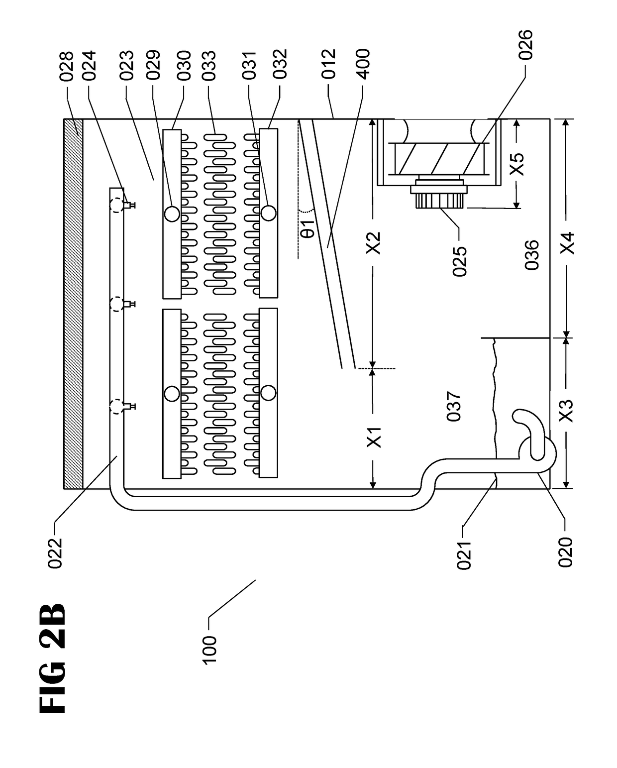
[0047]the present invention is shown in FIG. 4C. The eighth embodiment 520 describes an alternative arrangement to that of the sixth or seventh embodiments in which overlapping gutter water gutter system 501 is equipped with a cleaning system 521, to prevent clogging of the gutters. For each gutter assembly, the cleaning system is composed of a nozzle 522, water supply line 523, control valve 524 and connection to a water supply 525. Cleaning water can be water from the network, spray water from the sump, make-up water, recycled or any clean available pressurized water supply. The cleaning water source is not a limitation of the embodiment. Note that gutter cleaning system 521 can be added to all disclosed embodiments. Gutter assemblies of overlapping gutter water gutter system 521 of embodiment 520 could be similar to that of previous embodiments. Angle θ1 of the overlapping gutter water collection system 501 is typically greater than 0° and less than 80°, with optimal angle betwee...


PUM


Abstract

An improved water management system with improved airflow distribution for counterflow evaporative heat exchangers is provided. Such heat exchangers include open cooling towers, closed circuit cooling towers, and evaporative condensers. The improved water management system eliminates water splash out and the noise associated with water splashing. Further when the fan assemblies are located below the evaporative heat exchanger, the improved water management system keeps the fans dry and prevents freezing in subzero climates.

Description

BACKGROUND AND SUMMARY OF THE INVENTION[0001]This invention concerns evaporative cooling towers, fluid coolers and evaporative condensers, and specifically the amelioration of the air and spray water flow within the evaporative cooling equipment. This invention improves air distribution while reducing airflow resistance to increase the thermal capacity for a given footprint of the evaporative cooling tower. In addition, this invention seeks to provide self-cleaning, easy to access, inspect and maintain evaporative cooling equipment.[0002]The improvement in airflow distribution, and decrease in airflow resistance, is achieved by reducing the amount of obstruction and turns in the airflow path, and by opening the plenum area around the fan. Typical forced draft evaporative cooling equipment with side inlet fans have uneven airflow distribution to the heat exchanger arranged above the fan. Solid baffles or fan housings are typically arranged to shield the mechanical and fan components ...

Claims


Application Information

Patent Timeline
IPC IPC(8): F28F25/04F28F25/12
CPCF28F25/04F28F25/12F28F2025/005F28F25/06F28C1/14F28D1/0443F28D1/0461F28D1/0477F28D1/05316F28D5/02Y02B30/70
Inventor AUTH, CHRISTOPHERROUSSELET, YOHANNMALAMUD, DINAEGOLF, KEVINSZTOBRYN, LUKASZ
Owner BALTIMORE AIRCOIL CO INC
Why Eureka
Try Eureka