Laminated flat electric wire

a flat wire and flat wire technology, applied in the direction of electric/fluid circuit, laminated bus-bars, transportation and packaging, etc., can solve the problem that the influence of the tabs of the flat wire has not been given enough consideration, and achieve the effect of suppressing the variation of electric resistan

Active Publication Date: 2020-09-22
TOYOTA JIDOSHA KK
View PDF35 Cites 2 Cited by
  • Summary
  • Abstract
  • Description
  • Claims
  • Application Information

AI Technical Summary

Benefits of technology

[0008]According to the aspect of the disclosure, a pattern in which both the tabs are disposed outermost at both end portions in the flat electric wire, and thus electrical resistance between the tabs becomes relatively large, is avoided, and thus it is possible to suppress variation in electric resistance.
[0010]According to the aspect of the disclosure, it is possible to reduce types of parts of the laminated flat electric wire and reduce a manufacturing cost.
[0012]According to the aspect of the disclosure, it is possible to provide a laminated flat electric wire in which variation in electric resistance is suppressed by avoiding tab disposition in which electric resistance becomes relatively large in a plurality of flat electric wires.

Problems solved by technology

However, sufficient consideration has not been given to the influence of disposition of the tabs of the flat wire.

Method used


Image

  • Laminated flat electric wire
  • Laminated flat electric wire
  • Laminated flat electric wire

Examples


embodiment

[0045]An embodiment of the disclosure is configured based on the above. Hereinafter, this embodiment will be described in detail with reference to the drawings.

[0046]Configuration

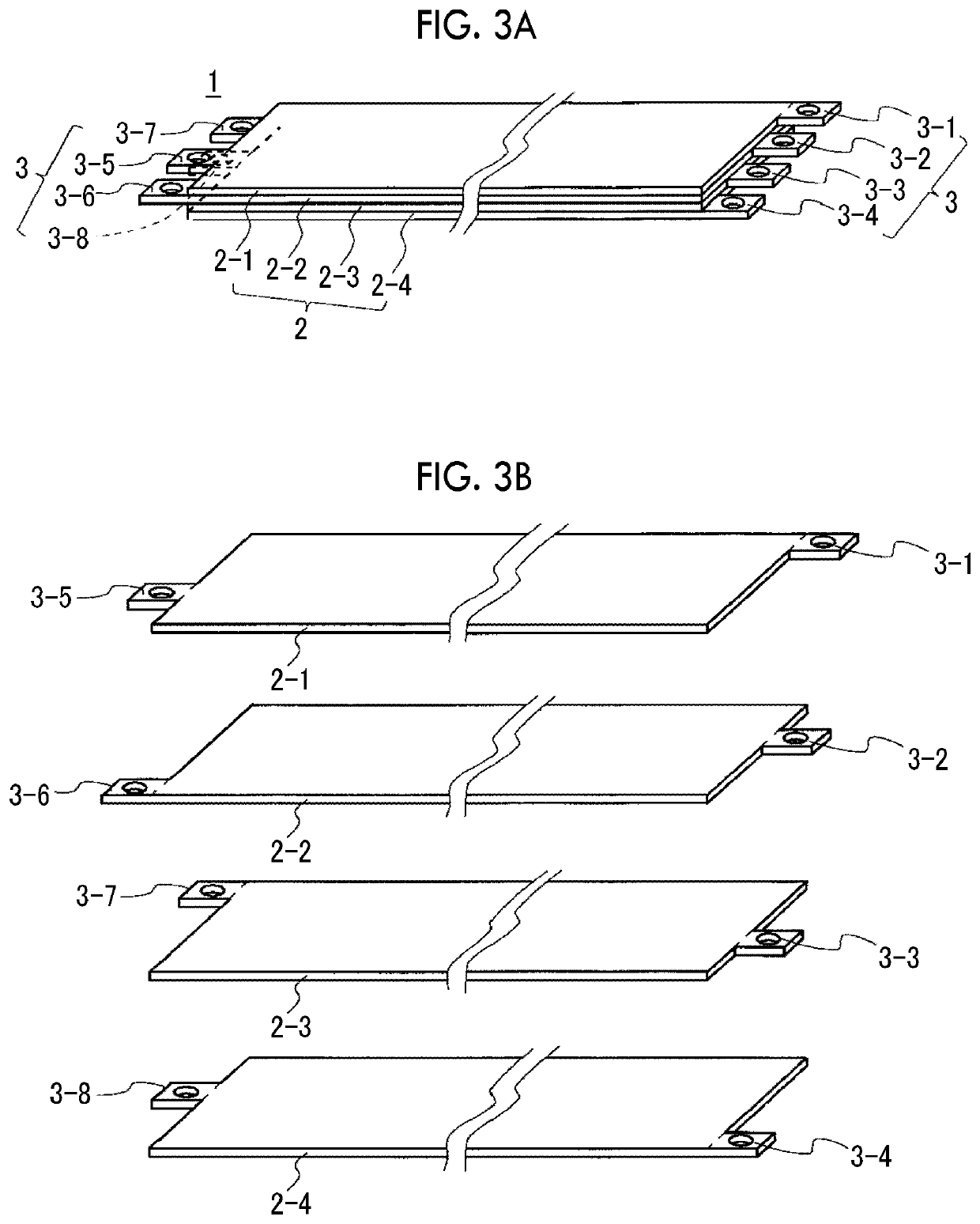
[0047]FIG. 3A shows a perspective view of a laminated flat electric wire 1 according to this embodiment. FIG. 3B shows an exploded perspective view of the laminated flat electric wire 1. FIG. 3C shows a plan view of the laminated flat electric wire 1 as viewed in the direction along the lamination direction. The laminated flat electric wire 1 includes four rectangular flat electric wires 2 (2-1 to 2-4), as an example. The respective flat electric wires 2 have insulating layers and are laminated in a state of being insulated from each other. The respective flat electric wires 2 include tabs 3 (3-1 to 3-4) extending from a first end portion in an extending direction. The respective flat electric wires 2 include tabs 3 (3-5 to 3-8) extending from a second end portion in the extending direction. Each of the tab...

example 1

of Branch Structure

[0055]An example of a branch structure using the laminated flat electric wire 1 as described above and a branch box will be described. FIG. 5A shows an exploded perspective view of a branch box 51 according to a first example. FIG. 5B shows a plan view of a main section in a state where a plurality of laminated flat electric wires 1 is mounted on the branch box 51.

[0056]The branch box 51 has four bus bars 52 (52-1 to 52-4) corresponding to the respective flat electric wires 2 between a substrate 54 and a lid 55. The bus bars 52 have insulating layers and are laminated in a state of being insulated from each other. Each of the bus bars 52-1 to 52-4 has a shape in which tabs 53 (53-1 to 53-4) respectively extend from four sides configuring a rectangular shape. Each of the tabs 53 has a hole, as an example, and an insulating layer is not formed on the tab 53.

[0057]By preparing a plurality of laminated flat electric wires 1 and fixing the respective tabs 3-1 to 3-4 an...

example 2

of Branch Structure

[0058]FIG. 6A shows an exploded perspective view of a main section of a branch box 151 according to a second example. FIG. 6B is a plan view showing a mounting direction of the laminated flat electric wires 1 on the branch box 151. FIG. 6C shows a perspective view of the main section in a state where the laminated flat electric wires 1 have been mounted on the branch box 151.

[0059]On a substrate 154 of the branch box 151, four bolts 152 (152-1 to 152-4) are provided perpendicularly to the substrate 154.

[0060]In the laminated flat electric wire 1, variation in electric resistance between the tabs 3 of the flat electric wire 2 is suppressed as described above, and therefore, even though the extension lengths of the tabs 3 are made different from each other, it is easy to keep variation in electric resistance within an allowable range. For this reason, in this example, the extension lengths of the tabs 3 are made different from each other within an allowable range, a...


PUM


Abstract

A laminated flat electric wire includes four or more rectangular plate-shaped flat electric wires. The flat electric wires are laminated, and each of the flat electric wires has tabs extending from each of the flat electric wires, one tab being provided at each of a first end portion and a second end portion. In a plan view as viewed in a direction along a lamination direction of the flat electric wires, the tabs of the respective flat electric wires are provided so as not to overlap each other at each of the first end portion and the second end portion, and the flat electric wire having the tab provided outermost along a width direction of the flat electric wire, among the respective tabs provided at the first end portions, has, at the second end portion, the tab provided at a position interposed between the tabs of other flat electric wires.

Description

INCORPORATION BY REFERENCE[0001]The disclosure of Japanese Patent Application No. 2017-231781 filed on Dec. 1, 2017 including the specification, drawings and abstract is incorporated herein by reference in its entirety.BACKGROUND1. Technical Field[0002]The disclosure relates to a laminated flat electric wire that is mounted on a vehicle or the like.2. Description of Related Art[0003]In a vehicle, a plurality of various electric wires for electric power supply from a battery or an alternator to various electrical components or for signal transmission between the electrical components is mounted. Various trunk line structures and branch structures for simplifying a mounting structure of electric wires in a vehicle is disclosed (Japanese Unexamined Patent Application Publication No. 2017-136926 (JP 2017-136926 A)).[0004]As an electric wire that is used for a vehicle or the like, a laminated flat electric wire in which a plurality of band-shaped flat electric wires is laminated in a sta...

Claims


Application Information

Patent Timeline
Patent Type & Authority Patents(United States)
IPC IPC(8): H02G5/00H01R11/12B60R16/02
CPCH02G5/005H01R11/12B60R16/0207
Inventor SAYO, TAKASHI
Owner TOYOTA JIDOSHA KK
Why Eureka
Try Eureka