Membrane electrode assembly and fuel cell

a technology of membrane electrodes and fuel cells, applied in cell components, fused electrolyte fuel cells, electrochemical generators, etc., can solve the problems of reducing the amount of use of noble metals without sacrificing electrical generation efficiency, unable to effectively utilize costly noble metal catalysts, and difficulty in reducing the amount of use of noble metals. , to achieve the effect of high surface pressure, high electrical current density, and high durability

Inactive Publication Date: 2010-10-26
TOYOTA JIDOSHA KK
View PDF18 Cites 1 Cited by
  • Summary
  • Abstract
  • Description
  • Claims
  • Application Information

AI Technical Summary

Benefits of technology

[0012]It is an object of the present invention to provide a membrane electrode assembly enabling electrical generation operation with high durability and high electrical current density, by allowing an electrode reaction to make effective use of a supported high-cost Noble metal catalyst and without applying high surface pressure by tightening. Another object of the present invention is to provide a fuel cell having the above-noted membrane electrode assembly, which achieves high electrical generation efficiency (electrical generation with a high current density) with high durability.
[0015]In this membrane electrode assembly, the first electrically conductive fibers that are oriented on the polymer electrolyte membrane side and the second electrically conductive fibers that are oriented on the diffusion layer side are caused to mutually contact one another. For example, one of the first electrically conductive fibers on the polymer electrode membrane side and second electrically conductive fibers on the diffusion layer side is interposed among the other electrically conductive fibers so as to make contact therewith, thereby forming a laminated structure of diffusion layer / catalyst layer / polymer electrolyte membrane in which strongly mutually intertwined electrically conductive fibers form the catalyst layer. The result is that the electrical resistance in the lamination direction (thickness direction) between the diffusion layer / catalyst layer / polymer electrolyte membrane is dramatically reduced, thereby enabling an improvement in the electrical conduction efficiency. For this reason, it is not necessary to apply high surface pressure using bolt tightening, which was essential in the past to achieve electrical generation performance (electrical conductivity), thereby eliminating the decrease in membrane durability accompanying the tightening, and enabling the achievement of good electrical generation performance (electrical generation operation at a high current density) and good durability.
[0016]A second aspect of the present invention relates to a fuel cell having the membrane electrode assembly of the first aspect and a separator in which a flow path is formed by a convex groove provided between a non-oriented region of the second electrically conductive fibers (for example, the layer surface on the side of the diffusion layer that is opposite from the side on which the second electrically conductive fibers are oriented) of the diffusion layer. By providing a membrane electrode assembly having this constitution, electrical generation operation is possible with high durability and at a high currently density.
[0017]According to the present invention, a membrane electrode assembly is provided that enables electrical generation operation with high durability and at a high current density, both with effective use made of the supported high-cost Noble metal catalyst for an electrode reaction and without applying a high surface pressure by tightening. The present invention also provides a fuel cell having this membrane electrode assembly, which achieves good electrical generation performance (electrical generation operation at a high current density) with high durability.

Problems solved by technology

That is, the reaction occurs with the supply of the reactant gas to the three phase boundary, and because, as shown in FIG. 4, the design of the three phase boundary is extremely difficult art, in the conventional art there was the problem of the insufficient supply of reactant gas to reach the three phase boundary, and a lack of effective utilization of the costly Noble metal catalyst supported in the region of the three phase boundary.
For this reason, even if an attempt is made to reduce the amount of Noble metal that is used, this leads to a decrease in the current supply, and it is difficult to reduce the amount of use of the Noble metal without sacrificing electrical generation efficiency.
Because it is particularly necessary to prevent a worsening of the contact resistance between the diffusion layer and catalyst layer and between the separator and the diffusion layer from reducing the electrical generation efficiency, it is essential that surface pressure be applied by tightening with bolts or the like, and there has been the problem of a worsening of membrane durability.
Particularly serious problems have been that of reducing the electrical contact resistance between the diffusion layer and catalyst layer and that of improving the diffusion of fuel and the like, that is, of achieving conductivity (for example, refer to Japanese Patent Application Publication No.
However, because the constitution is one in which a layer of only carbon particles is provided as a diffusion layer on the catalyst electrode, although there is a small reduction in the internal resistance, the gas diffusion is not improved, and this is insufficient from the standpoint of improving the electrical generation efficiency.
However, with a constitution in which the carbon is merely made fibrous, this is similar to the above-noted related art in that the electrical generation efficiency is insufficient, and in that a detrimental effect on the membrane durability is not avoided.
As described above, although reducing the internal resistance in a fuel cell is effective in increasing the electrical generation efficiency of the fuel cell, the effectiveness of merely adding a diffusion layer using carbon paper or the like in improving the contact resistance is poor.
Also, related art has not been established for effectively utilizing, in the electrode reaction, the Noble metal catalyst, which is carried in the region of the three phase boundary that is at a distance from the supply side of the fuel and oxidant gas.
That is, the current situation with related art is that it is not yet possible to provide a membrane electrode assembly capable of achieving good electrical generation efficiency without applying high surface pressure by tightening, which adversely affects the membrane.

Method used


Image

  • Membrane electrode assembly and fuel cell
  • Membrane electrode assembly and fuel cell
  • Membrane electrode assembly and fuel cell

Examples


Embodiment Construction

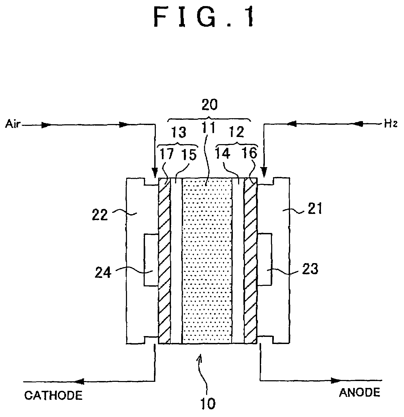
[0023]An embodiment of a fuel cell according to the present invention is described in detail below, with references made to the accompanying drawings, and the embodiment of a membrane electrode assembly according to the present invention will also be described in detail as part of that description. In the embodiment described below, the description is mainly with respect to a solid polymer fuel cell (PEFC) using hydrogen gas and air (oxygen) as fuel for electrical generation operation. It will be understood, however, that the present invention is not restricted to the embodiments described below.

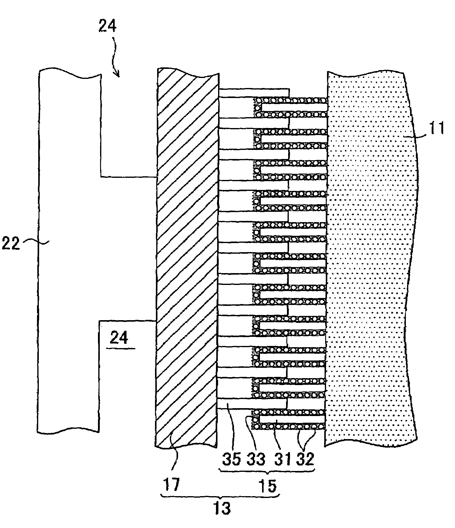
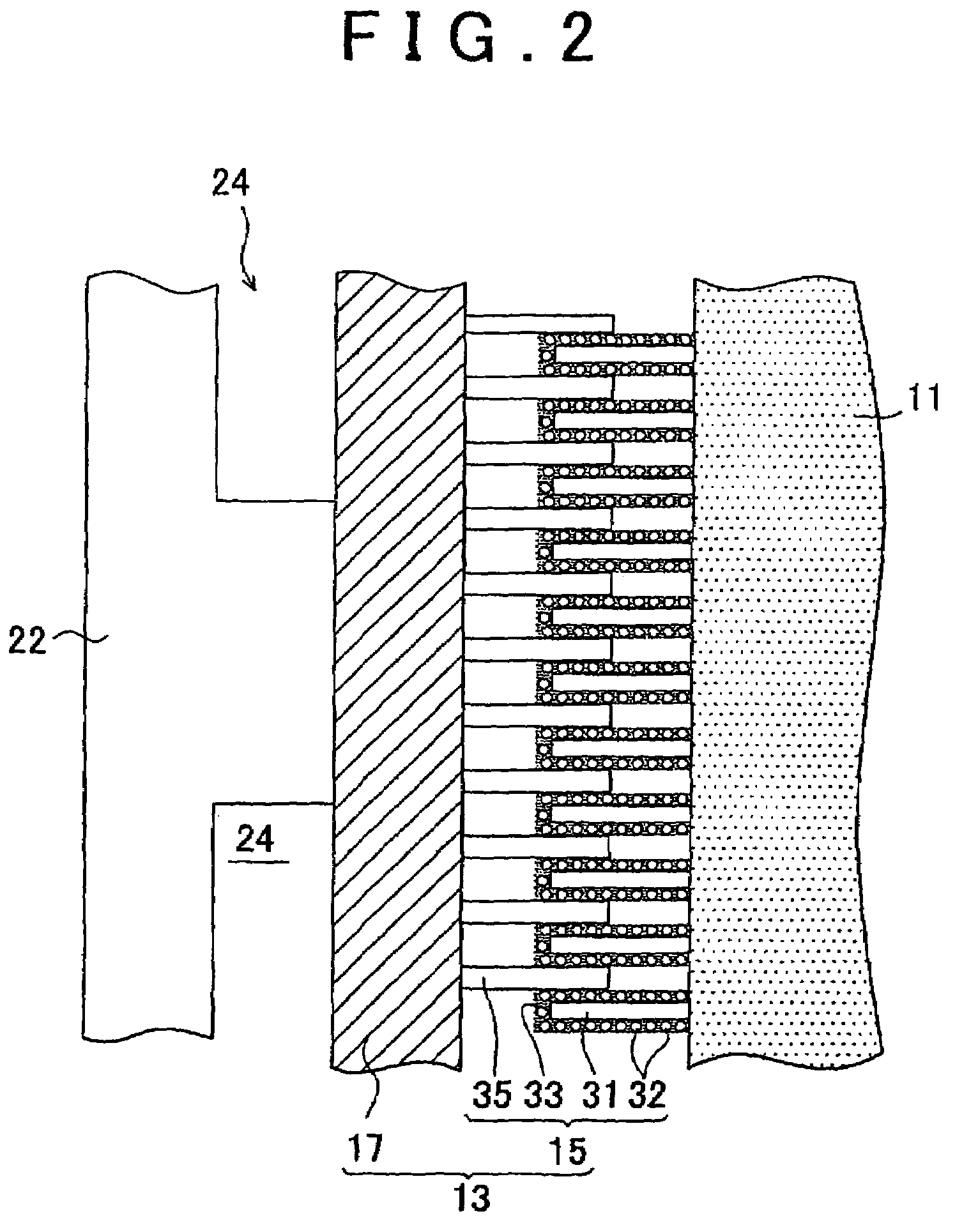
[0024]An embodiment of a membrane electrode assembly and a fuel cell according to the present invention is described below with references made to FIG. 1 to FIG. 3. This embodiment uses single-layer carbon nanotubes 31, 35 (hereinafter single-layer carbon nanotube are sometimes abbreviated as CNT) as the electrically conductive fibers. The linear Pt-carrying CNT 31 that carries platinum (Pt;...


PUM

PropertyMeasurementUnit
thicknessaaaaaaaaaa
lengthaaaaaaaaaa
lengthaaaaaaaaaa

Abstract

A membrane electrode assembly includes a fluorine-based ion exchange resin membrane, a diffusion layer and a catalyst layer that supports a battery reaction. The catalyst layer is formed from Pt-carrying carbon nanotubes that is oriented on the fluorine-based ion exchange resin membrane, and non-Pt-carrying carbon nanotubes that is oriented on the diffusion layer.

Description

INCORPORATION BY REFERENCE[0001]The disclosure of Japanese Patent Application No. 2004-111856 filed on Apr. 6, 2004 including the specification, drawings, and abstract is incorporated herein by reference in its entirety.BACKGROUND OF THE INVENTION[0002]1. Field of the Invention[0003]The present invention relates to a membrane electrode assembly applied to an electricity generating cell of a fuel cell using a polymer electrolyte membrane, and to a fuel cell using same.[0004]2. Description of the Related Art[0005]In recent years, fuel cells that generate electricity by electrochemical reactions between hydrogen and oxygen have become the subject of interest as an energy supply source. In a fuel cell, for example, using an ion exchange resin membrane, the configuration is generally one in which the ion exchange resin membrane made of a polymer electrolyte is sandwiched between an anode electrode and a cathode electrode. Each of these electrodes is constructed so as to be provided with ...

Claims


Application Information

Patent Timeline
Patent Type & Authority Patents(United States)
IPC IPC(8): H01M8/14
CPCH01M4/926H01M8/1004H01M4/921H01M2008/1095Y02E60/523Y02E60/50
Inventor NAKANISHI, HARUYUKI
Owner TOYOTA JIDOSHA KK
Why Eureka
Try Eureka