Female member of snap fastener and resin spring used therein
a technology of resin springs and snap fasteners, which is applied in the direction of snap fasteners, press-button fasteners, apparel, etc., can solve the problems of difficult to accurately align the opposing spring elements of the resin spring with each other, metal springs that make squeaky sounds, and are susceptible to corrosion, so as to prevent movement, prevent noise, and excellent chemical resistance
- Summary
- Abstract
- Description
- Claims
- Application Information
AI Technical Summary
Benefits of technology
Problems solved by technology
Method used
Image
Examples
embodiment 1
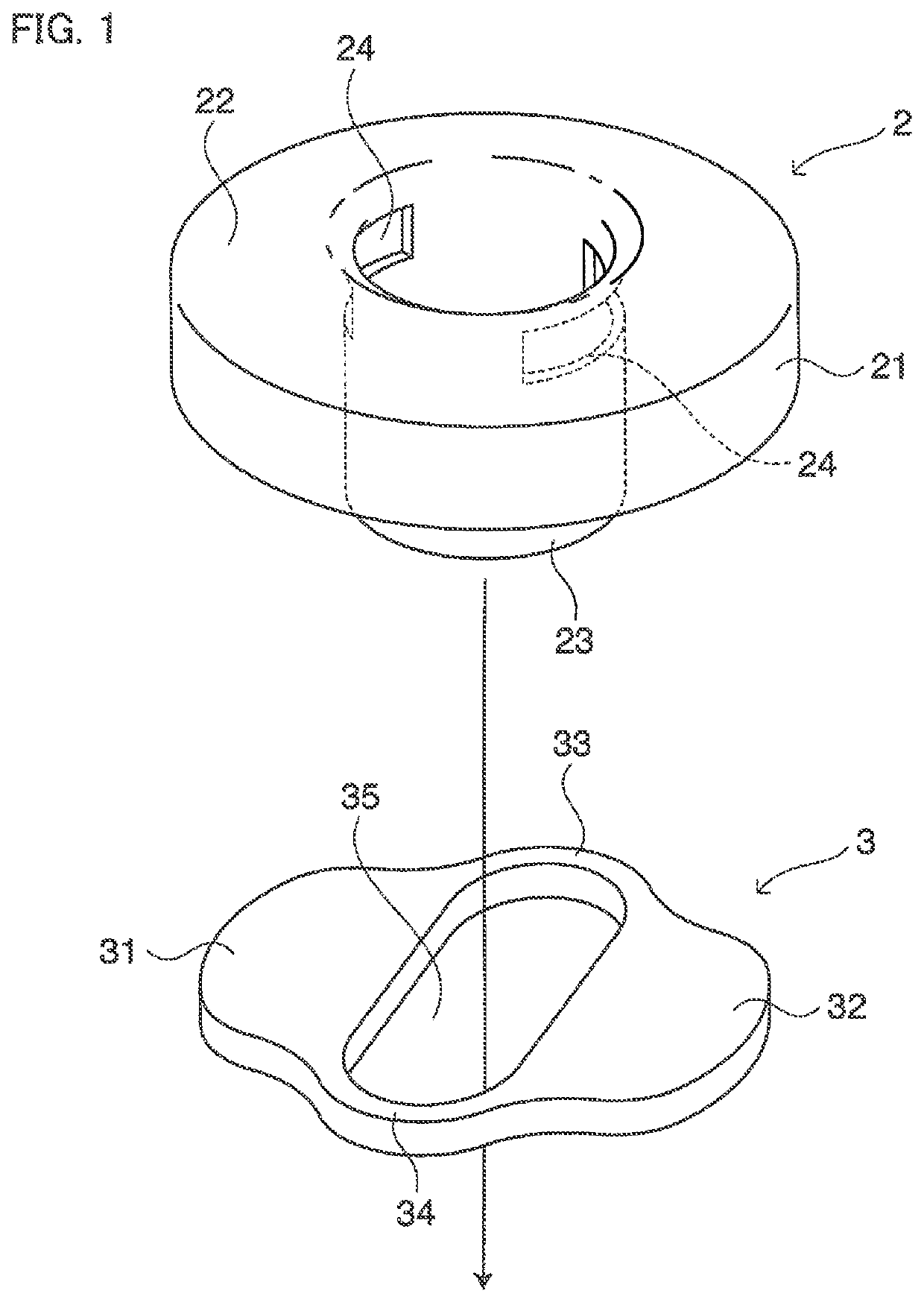
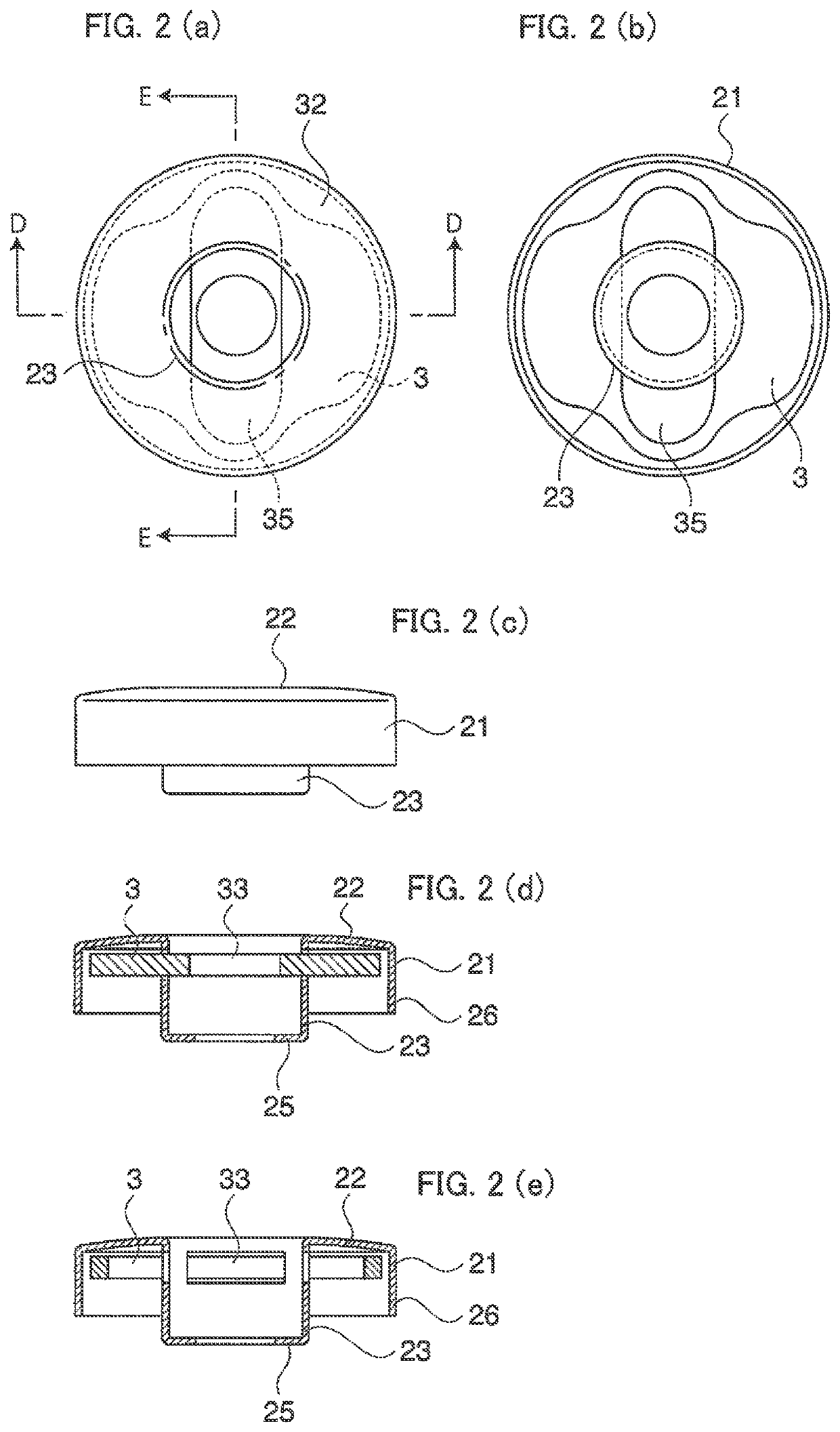
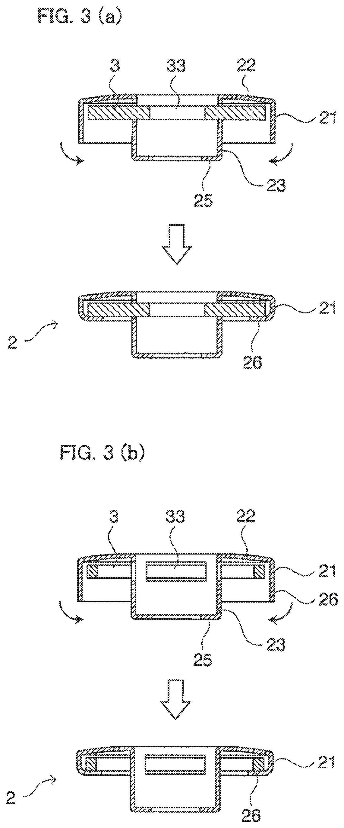
[0035]FIGS. 1 and 2 show a main body 2 and a resin spring 3 that are components constituting a female member 1 of a snap fastener.
[0036]The main body 2 is made of a metal such as brass, and has a dish-shaped portion 22 having a rim portion 21 and a cylindrical tube portion 23 protruding from the center of the dish-shaped portion 22. It is preferable that the entire main body 2 is integrally formed through deep drawing. A letter or a figure (not shown) can be inscribed on a surface of the dish-shaped portion 22. The cylindrical tube portion 23 has two slits 24 that are placed near the base thereof and oppose each other, and a leading end of the cylindrical tube portion 23 is bent in an inward direction of the cylindrical tube to form an inward flange 25.
[0037]The resin spring 3 is shaped like a handguard of a Japanese sword, and has a slot 35 that is formed by left and right wide portions 31 and 32 as well as upper and lower narrow portions 33 and 34 and extends in the vertical direc...
embodiment 2
[0045]A resin spring 3A in FIG. 5 has a slit 36 in one narrow portion 34A Since the strength is reduced, it is preferable to increase the length in the upper-lower direction of a narrow portion 33A that opposes the narrow portion 34A.
embodiment 3
[0046]A resin spring 3B in FIG. 6 has wire springs 37 and 38 instead of the wide portions 31A and 32A Each wire spring extends in a circular arc shape from near a corresponding one end portion of the slot in the longitudinal direction along the rim portion of the dish-shaped portion. With this configuration, a weight reduction can be achieved.
PUM
| Property | Measurement | Unit |
|---|---|---|
| thickness | aaaaa | aaaaa |
| length | aaaaa | aaaaa |
| width | aaaaa | aaaaa |
Abstract
Description
Claims
Application Information
 - R&D
- Intellectual Property
- Life Sciences
- Materials
- Tech Scout
- Unparalleled Data Quality
- Higher Quality Content
- 60% Fewer Hallucinations
Browse by: Latest US Patents, China's latest patents, Technical Efficacy Thesaurus, Application Domain, Technology Topic, Popular Technical Reports.
© 2025 PatSnap. All rights reserved.Legal|Privacy policy|Modern Slavery Act Transparency Statement|Sitemap|About US| Contact US: help@patsnap.com


