Separating device

a separation device and separation technology, applied in the direction of combination devices, membrane filters, dispersed particle filtration, etc., can solve the problems of complex design implementation and lack of known solutions for separating performance, and achieve cost-effective implementation, reliable operation, and save installation space

Active Publication Date: 2020-09-29
FILTERTECHN
View PDF27 Cites 3 Cited by
  • Summary
  • Abstract
  • Description
  • Claims
  • Application Information

AI Technical Summary

Benefits of technology

[0006]Based upon this prior art, an object of the invention to further improve the known solutions in such a way that a separating device is provided that saves on installation space, can be implemented cost-effectively and still performs reliably in operation at a high degree of separation.
[0007]This object is basically met by a separating device where a spiral-shaped guiding device for the medium flow is provided with a plurality of individual spiral arms. The individual spiral arms are arranged in adjacent pairs and delimit radially extending flow spaces located opposite to each other in such a way that the medium flow is directed outwards. A high degree of separation of contaminants from the gaseous medium flow is then achieved in a functionally reliable manner because of the plurality of fixed, spiral-shaped guide vanes of the spiral separator. Moreover, the spiral separator can be produced in a cost-effective and space-saving manner. This structure has no equivalent in the prior art.
[0008]In a preferred embodiment of the separating device according to the invention, the medium flow, which is present particularly in form of a gas stream contaminated with solid particles, such as dust-laden, surrounding air, is supplied via a medium inlet of a housing of the device, axially to a central area of the guiding device, in which the individual spiral arms of the guiding device meet. In particular, where the medium inlet opening gradually reduces in the direction of the guiding device, the medium flow can initially be sped up prior to a uniform distribution into the distribution chambers of the spiral separator delimited by the spiral arms. This structure is favourable for the further acceleration via the spiral-shaped vanes of the guiding device in radial direction when viewed outwards.
[0012]In a further preferred embodiment of the separating device according to the invention, all spiral arms of the guiding device are the same. In particular they all have the same length and the same height, so that the rotationally symmetrical spiral separator can be disposed inside the housing of the separating device in any desired installation direction in longitudinal direction. Moreover, that spiral separator with its fixed spiral arms that form the guide vanes of the guiding device can be produced cost-effectively, for example, as an injection-moulded plastic component. Due to the symmetrical design of the spiral separator, an equally good discharge rate is achieved for the medium flow as well as for the desired separation rate in every direction of the spiral separator.
[0014]The air filtration system may preferably be provided with a main filter element with greater filter fineness and a safety filter element with reduced filter fineness that is disposed concentrically inside the main filter element or which is located downstream. In the instance that this air filter element in form of the main filter element has to be replaced with a new element once it has been subjected to particulate contamination, and the main filter element is accidentally left out during the intended exchange, the safety filter element would perform a sufficiently high level of separation of any remaining particulate contamination in the operation of the separating device without causing any damage to the combustion engine.

Problems solved by technology

Nevertheless, this design is complex in implementation, and thus, expensive.
Nevertheless, the known solution is lacking with respect to its separating performance in removing liquid as contaminants from the flow of gaseous media.

Method used


Image

  • Separating device
  • Separating device
  • Separating device

Examples


Embodiment Construction

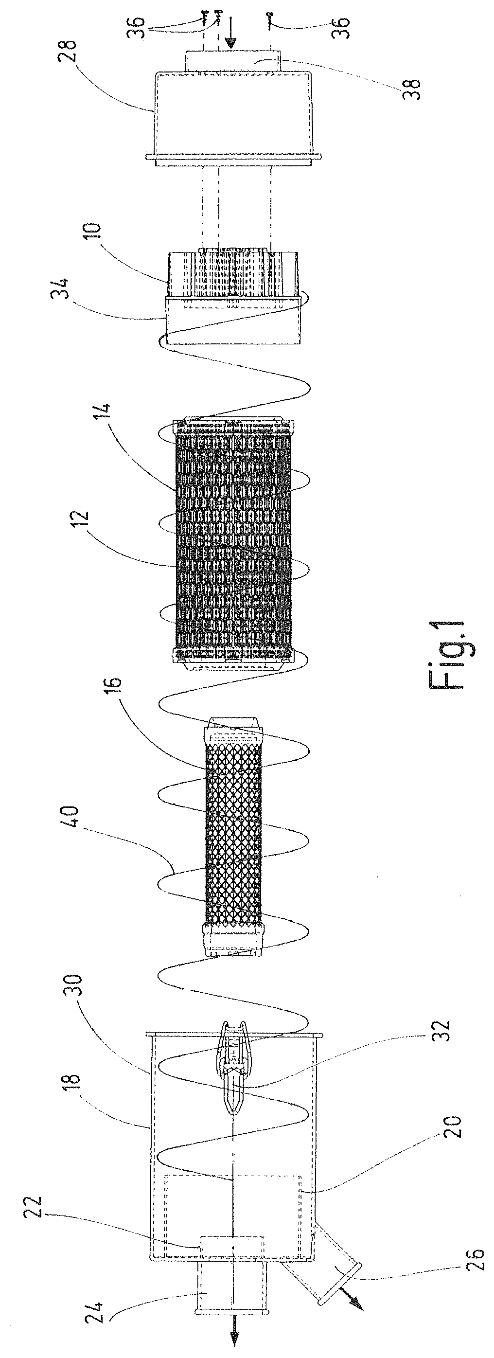
[0025]The separating device shown in FIG. 1 shows, as pre-separator, a spiral separator 10, attached, in flow direction of a medium, in particular in form of a gas or air stream, to an air filtration system 12 comprising a main filter element 14 and a safety filter element 16. The main filter element 14 takes the form of a hollow cylinder and is comprised of a filter medium with greater filter fineness. The main filter element 14 is able to house the safety filter element 16 concentrically inside it. The safety filter element 16 also takes the form of a hollow cylinder, but its filter medium is of a lesser filter fineness compared to that of the main filter element 14. Both filter elements 14, 16 may be disposed inside a pot-shaped lower housing part 18. To facilitate this, the lower housing part 18 is provided with an integrated connection socket 20 to connect to the end of the main filter element 14, as well as with a further integrated socket 22 to connect to the one end of the s...


PUM

PropertyMeasurementUnit
distanceaaaaaaaaaa
widthaaaaaaaaaa
lengthaaaaaaaaaa

Abstract

A separating device, particularly a spiral separator (10), separates impurities, particularly in the form of solids, from a gaseous medium flow, such as air. The medium can be fed to a spiral-shaped guiding device (42) that brings about an at least partial separation of the respective impurities from the medium flow. The guiding device (42) has a plurality of spiral arms (44) that delimit radially extending flow spaces (46) and that are arranged in an adjacent manner opposite to one another such that the medium flow is guided radially outwards.

Description

FIELD OF THE INVENTION[0001]The invention concerns a separating device, in particular in the manner of a spiral separator, for the separation of solids from a gaseous medium flow, which may be fed into a spiral-shaped guiding device.BACKGROUND OF THE INVENTION[0002]DE 10 2010 014 278 A1 discloses a cyclone separator for the separation of liquid and / or solid particles from a gaseous flow, comprising a first cyclone component with at least one, essentially cylindrical, cell pipe that is provided with a guiding device, which may be used to cause the gas flow to go into rotation for the purpose of separating the particles. Moreover, the known solution is provided with a particle outlet to discharge the separated particles from the device, as well as a second cyclone component, disposed subsequently in flow direction of the gas flow, with at least one immersion pipe that is contained inside the cell pipe, and which is at least partially attached to the downstream end of the cell pipe, fo...

Claims


Application Information

Patent Timeline
Patent Type & Authority Patents(United States)
IPC IPC(8): B01D50/00B01D45/16B01D45/08B01D46/24B01D46/00
CPCB01D45/16B01D50/002B01D46/0024B01D45/08B01D46/0045B01D46/2403B01D2267/40B01D46/64B01D50/20
Inventor OBERLI, FRANKSTEICHE, ANDREASKESSEL, ROBERT
Owner FILTERTECHN
Why Eureka
Try Eureka