
Method and control unit for operating a gradient coil device of an MRI system or another periodically stressed device

a gradient coil and periodic stress technology, applied in the direction of measuring devices, magnetic measurements, instruments, etc., can solve the problem of sixteen-times the damage potential of stress (or velocity) at double amplitude, and achieve the effect of less sharpness

Active Publication Date: 2020-09-29
KONINKLJIJKE PHILIPS NV
View PDF12 Cites 0 Cited by
  • Summary
  • Abstract
  • Description
  • Claims
  • Application Information

AI Technical Summary

Benefits of technology

[0011]The model uses at least one measured or calculated first parameter of the device based on velocities in the power b (corresponding to the Wöhler curve). According to the document ‘F. V. Hunt: “Stress and Strain Limits on the Attainable Velocity in Mechanical Systems”, JASA, 32(9) 1123-1128, 1960.’ velocity is the property that scales best with mechanical stress as function of frequency. The model can also use a different power than the power 4. For example using a power 2 makes the filters less sharp.

Problems solved by technology

This means that the damage potential of a stress (or velocity) at double amplitude is sixteen times as severe in contributing to mechanical fatigue.

Method used


Image

  • Method and control unit for operating a gradient coil device of an MRI system or another periodically stressed device
  • Method and control unit for operating a gradient coil device of an MRI system or another periodically stressed device

Examples


Embodiment Construction

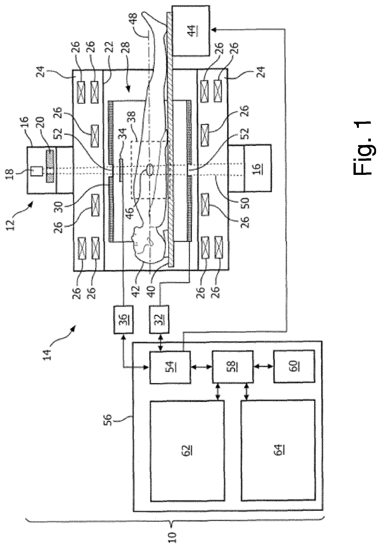
[0033]FIG. 1 shows an embodiment of an MR-guided radiation therapy system 10. The MR-guided radiation therapy system 10 comprises a LINAC 12 and a magnetic resonance imaging system (MRI system) 14 according to the invention. The LINAC 12 comprises a gantry 16 and a X-ray source 18. The gantry 16 is for rotating the X-ray source 18 about an axis of gantry rotation 20. Adjacent to the X-ray source 18 is an adjustable collimator 20. The adjustable collimator 20 may for instance have adjustable plates for adjusting the beam profile of the X-ray source 18. The adjustable collimator 20 may, for example, be a multi-leaf collimator. The magnetic resonance imaging system 14 comprises a magnet 22.

[0034]It is also possible to use permanent or resistive magnets. The use of different types of magnets is also possible for instance it is also possible to use both a split cylindrical magnet and a so called open magnet. A split cylindrical magnet is similar to a standard cylindrical magnet, except t...


PUM


Abstract

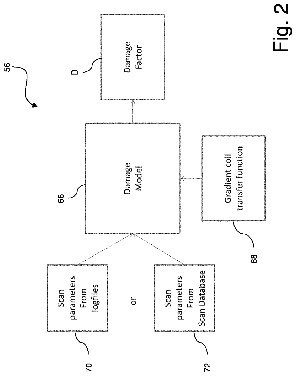
A control unit (56) operates a gradient coil device of a magnetic resonance imaging system (14). At least one first parameter of the gradient coil device (30) and / or at least one second parameter of the gradient coil device (30) is provided. A damage calculation of an operation of the gradient coil device (30) is performed by use of a mathematical model (66), which model (66) is based on the stress-cycle curve or a modified stress-cycle curve and uses the at least one first parameter (68) and / or the at least one second parameter (70, 72). Second parameters for further operation of said gradient coil device (30) are determined.

Description

CROSS REFERENCE TO RELATED APPLICATIONS[0001]This application is a U.S. national phase application of International Application No. PCT / EP2017 / 069100, filed on Jul. 28, 2016, which claims the benefit of EP Application Serial No. 16181603.8 filed on Jul. 28, 2016 and is incorporated herein by reference.FIELD OF THE INVENTION[0002]The invention relates to a method for operating a gradient coil device of a magnetic resonance imaging system[0003]The invention further relates to a corresponding control unit for operating a gradient coil device of a magnetic resonance imaging system and a corresponding magnetic resonance imaging system comprising a gradient coil device and a control unit.BACKGROUND OF THE INVENTION[0004]Document US 2015 / 0369888 A1 describes a method for operating a gradient coil device of a magnetic resonance imaging system including a modelling of vibrations of the gradient coil device with the aim to reduce acoustic noise during operation of said device.[0005]Gradient c...

Claims


Application Information

Patent Timeline
Patent Type & Authority Patents(United States)
IPC IPC(8): G01R33/385
CPCG01R33/3854G01R33/385
Inventor TERMEER, MARTIJN KRELIS
Owner KONINKLJIJKE PHILIPS NV
Learn More