Display device

a technology of a display device and a display screen, applied in the field of display devices, can solve problems such as leakage of light from an led, and achieve the effect of less sharpness

Active Publication Date: 2018-10-09
FUNAI ELECTRIC CO LTD
View PDF6 Cites 0 Cited by
  • Summary
  • Abstract
  • Description
  • Claims
  • Application Information

AI Technical Summary

Benefits of technology

[0007]With the above-mentioned Patent Literature 1, the reflective-walled channels and the rear face of the light modulator are perpendicular. Thus, part of the light from the LEDs that has a relatively large angle with respect to a direction perpendicular to the rear face of the light modulator maintains its angle with respect to the rear face while being reflected inside the reflective-walled channels and moving closer to the light modulator. This results in that the light from an LED leaks from a gap between the light modulator and a corresponding reflective-walled channel into areas corresponding to other LEDs. As a result, the contrast of the display device tends to be less sharp between the areas corresponding to the LEDs on the light modulator.
[0008]One object of the present disclosure is to provide a display device with which sharper contrast between the areas corresponding to light sources on a display can be achieved.

Problems solved by technology

This results in that the light from an LED leaks from a gap between the light modulator and a corresponding reflective-walled channel into areas corresponding to other LEDs.

Method used


Image

  • Display device
  • Display device
  • Display device

Examples


first embodiment

[0022]The configuration of a display device 100 in accordance with a first embodiment will be described through reference to FIGS. 1 to 8.

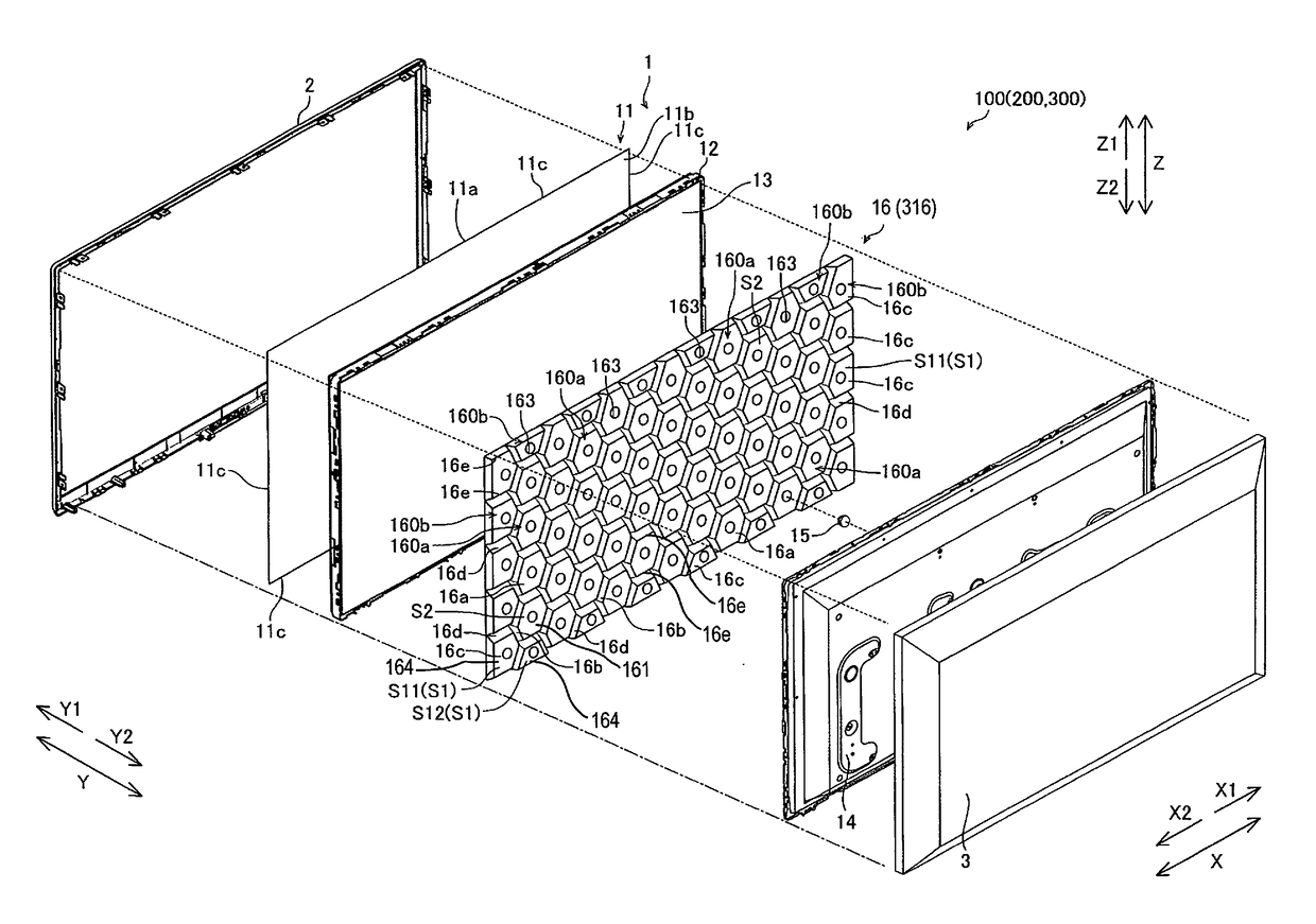
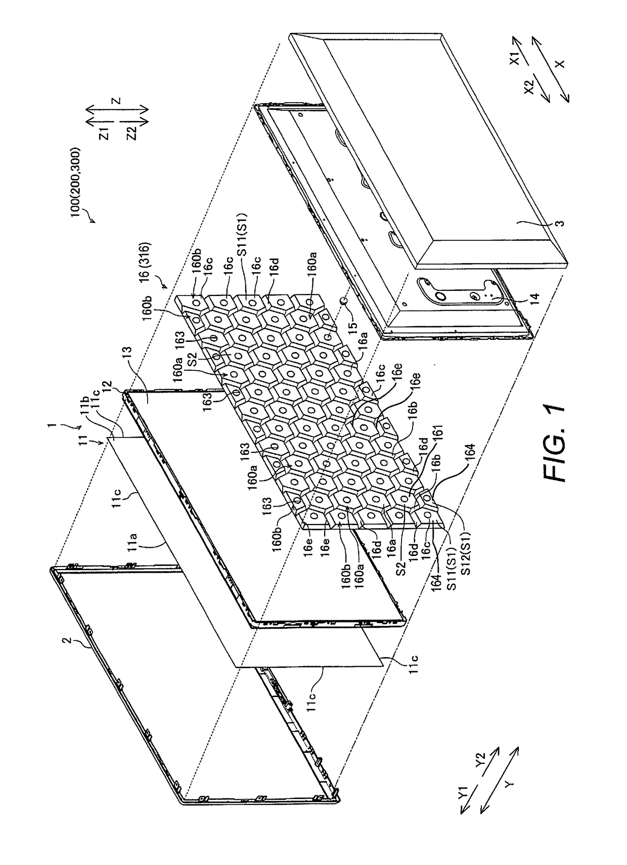
[0023]As shown in FIG. 1, the display device 100 includes a display module 1, a front cabinet 2 and rear cabinet 3. The front cabinet 2 and the rear cabinet 3 house the display module 1.

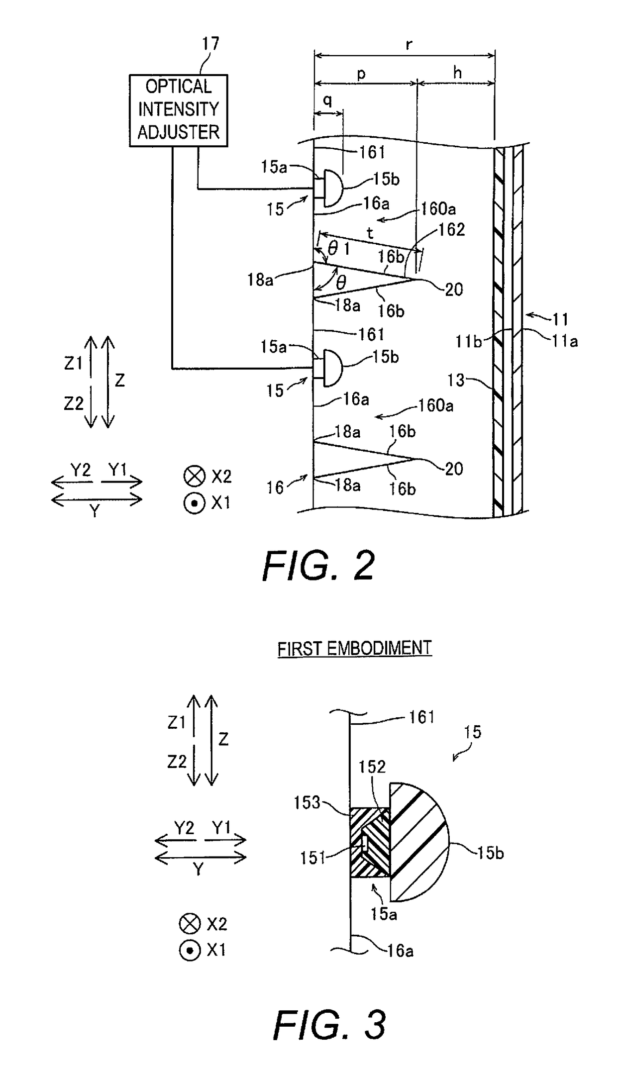
[0024]The display module 1 includes at least a liquid crystal cell 11 (e.g., a display panel or a display), at least one optical sheet 13 (e.g., a light processing member), a plurality of light sources 15, and a reflective sheet 16. In the illustrated embodiment, the display module 1 also includes a light intensity adjuster 17 (see FIG. 2). In the illustrated embodiment, the display module 1 also includes a molding frame 12 that holds the liquid crystal cell 11, and a rear frame 14. The liquid crystal cell 11 is an example of the “display” in the present disclosure. Also, the optical sheet 13 is an example of the “light processing member” in the present disclosure....

second embodiment

[0074]A second embodiment will now be described through reference to FIGS. 1 and 9. In the first embodiment above, the light from the light emitting elements 151 is emitted substantially uniformly in the peripheral direction by providing the lens components 15b. On the other hand, in the second embodiment, the light from the light emitting elements 151 is emitted substantially uniformly in the peripheral direction without providing lens components.

[0075]As shown in FIG. 9, with the display device 200 in accordance with the second embodiment (see FIG. 1), light sources 215 each include a light emitting element package 215a having a light emitting element 151, a sealing component 152, and a reflector 253 disposed to the rear of the light emitting element 151 and the sealing component 152.

[0076]The reflectors 253 are formed in a circular shape. The reflectors 253 are configured to reflect light from the light emitting elements 151 substantially uniformly in the peripheral direction. Th...

third embodiment

[0082]A third embodiment will now be described through reference to FIG. 1. In the first embodiment above, the first bottom parts 16a, the first peripheral parts 16b, the second bottom parts 16c and the second peripheral parts 16d are formed by folding a single reflective sheet 16. On the other hand, in the third embodiment, the first bottom parts 16a, the first peripheral parts 16b, the second bottom parts 16c and the second peripheral parts 16d are formed by integral molding using a metal mold.

[0083]As shown in FIG. 1, the display device 300 in accordance with the third embodiment (see FIG. 1) includes a reflective member 316. The first bottom parts 16a, the first peripheral parts 16b, the second bottom parts 16c and the second peripheral parts 16d are formed integrally with the reflective member 316 by injection molding using a metal mold. More specifically, the first bottom parts 16a, the first peripheral parts 16b, the second bottom parts 16c and the second peripheral parts 16d...


PUM

PropertyMeasurementUnit
angle θ1aaaaaaaaaa
angle θ1aaaaaaaaaa
angles θ2aaaaaaaaaa

Abstract

A display device includes a display, a plurality of first reflectors, a light processing member, and a plurality of light sources. The first reflectors each have a first bottom part that is disposed on a rear face side of the display and a first peripheral part that extends from an outer edge of the first bottom part toward a rear face of the display, with a surface of the first bottom part and a surface of the first peripheral part forming an obtuse angle. The light processing member is disposed between the display and the first reflectors, the light processing member being spaced apart from the first reflectors by a specific distance. The light sources are disposed relative to the surfaces of the first bottom parts, respectively.

Description

CROSS-REFERENCE TO RELATED APPLICATIONS[0001]This application claims priority to Japanese Patent Application No. 2016-146235 filed on Jul. 26, 2016. The entire disclosure of Japanese Patent Application No. 2016-146235 is hereby incorporated herein by reference.BACKGROUND[0002]Field of the Invention[0003]The present invention generally relates to a display device. More specifically, the present invention relates to a display device having a reflecting member that reflects light from a light source towards a display.[0004]Background Information[0005]Display devices having a reflecting member that reflects light from a light source towards a display are well known in the art.[0006]Japanese Translation of PCT International Application Publication No. 2005-520188 (Patent Literature 1) discloses a display device having a light modulator, a plurality of reflective-walled channels, a plurality of LEDs, and a diffuser. The reflective-walled channels are disposed on a rear face side of the li...

Claims


Application Information

Patent Timeline
Patent Type & Authority Patents(United States)
IPC IPC(8): H01L51/50G02F1/00G02F1/1335H01L51/52
CPCH01L51/5012G02F1/0063H01L51/5044G02F1/133605H01L51/5265G02F1/133553G09F9/00H10K50/11H10K50/131H10K50/852
Inventor YAMASHITA, HIROSHI
Owner FUNAI ELECTRIC CO LTD
Why Eureka
Try Eureka