Collimator and a lighting unit

a lighting unit and collimator technology, applied in the field of collimators and lighting units, can solve the problems of inability to achieve the depth required by a single light source, inconvenient operation, and inability to remove light, so as to reduce the beam angle, reduce the effect of beam angle and large angl

Active Publication Date: 2021-07-20
SIGNIFY HLDG BV
View PDF28 Cites 0 Cited by
  • Summary
  • Abstract
  • Description
  • Claims
  • Application Information

AI Technical Summary

Benefits of technology

[0019]This collimator design provides blocking of light to the central lens of a Fresnel structure. In particular, at some or all parts of the inner lens portion, light does not reach those parts from the full area of the light source. This partial light blocking can be used to reduce the beam angle reaching the inner lens portion (by blocking light at larger angles) but it is also possible to block light from the center and allow more to reach larger angles. In all cases, by having areas where the whole shape of the light source is not projected onto the inner lens portion or in other words, the inner lens portion has areas where only a portion of the whole shape of the light source is projected onto, the halo effect described above can be reduced or eliminated, if desired.
[0020]The blocking element makes the light distribution of the center lens narrower, less sharp and helps to eliminate color artifacts from the source. While the efficiency of the spot is inevitably reduced, the peak intensity can be maintained.
[0024]The light blocking element for example comprises a conical baffle. This provides a light narrowing function, which limits the angular spread of light reaching the central part, and optionally also the radial outer part of the lens. This may be achieved by having an opening to the conical baffle which is smaller than the light source (or smaller than the beam envelope from the light source to the outer edge of the inner lens portion).
[0033]In another set of examples, the light blocking element may comprise a set of radially extending fins disposed in an annular arrangement. These fins block skew rays, which may be incident on the inner lens portion because the light source has a finite light output area (i.e. it is not a point source). Thus, the light blocking element reduces skewness.

Problems solved by technology

In many LED devices, the depth required by a single light source is unavailable since other parts of the device, such as the heat sink and driver, take up a significant proportion of the available space.
Such light is in many cases unwanted, because it creates a halo around the main beam, which often has a sharp, very visible edge.
The center lens, especially because of its imaging characteristics, is problematic when used with COB sources, because the edge of such sources emits fully converted yellowish light.
The center lens puts such light at the edge of the light distribution, thus creating a yellow outermost ring around the light distribution, which is not desired.
The problem of the large center lens images is linked to the geometrical constraints of typical TIR Fresnel collimators.
In other words, there is too high etendue in the center lens section.
To make such a louver device efficient, it needs to be of very thin material, e.g. metal, which makes it expensive.
It thus adds volume and cost to the design.

Method used


Image

  • Collimator and a lighting unit
  • Collimator and a lighting unit
  • Collimator and a lighting unit

Examples


Embodiment Construction

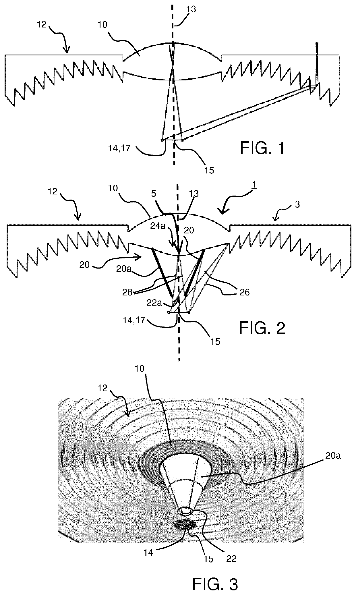
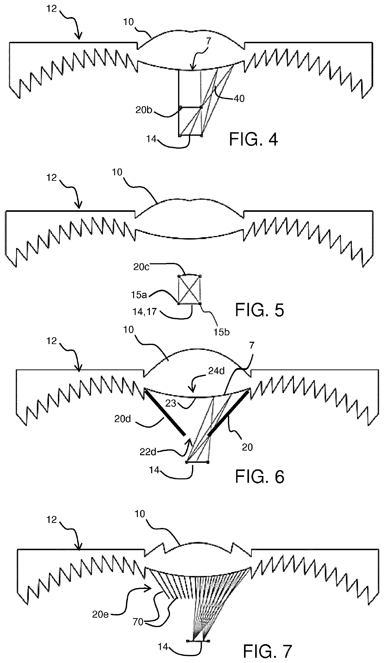
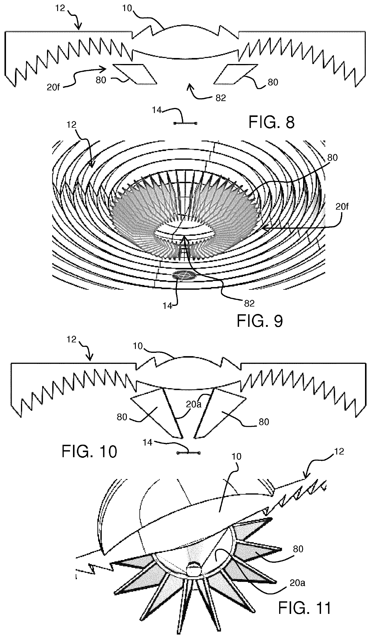
[0057]The invention provides a collimator comprising a Fresnel lens having a focal point and comprising a refractive lens portion and a toothed total internal reflection portion. A light blocking element is at least between the lens portion and the light source provided in a light source position. A portion of a light source output is blocked from reaching at least one region of the inner lens portion. At some or all parts of the lens portion, light does not reach those parts from the full area of the light source. This partial light blocking means the whole shape of the light source is not projected onto all of the lens portion, and the halo effect is reduced or eliminated. This serves to reduce the etendue of the light source and reduces the beam angle of the center lens, its imaging characteristics, the yellow ring problem and glare issues.

[0058]The light blocking element can be reflective to recycle part of the light by sending light back to the source or it can be absorbing.

[00...


PUM


Abstract

The invention provides a collimator comprising a Fresnel lens comprising a refractive lens portion and a toothed total internal reflection portion. A light blocking element is at least between the lens portion and the light source. A portion of a light source output is blocked from reaching at least one region of the inner lens portion. At some or all parts of the lens portion, light does not reach those parts from the full area of the light source. This partial light blocking means the whole shape of the light source is not projected onto all of the lens portion, and the halo effect is reduced or eliminated.

Description

CROSS-REFERENCE TO PRIOR APPLICATIONS[0001]This application is the U.S. National Phase application under 35 U.S.C. § 371 of International Application No. PCT / EP2018 / 055012, filed on Mar. 1, 2018, which claims the benefit of European Patent Application No. 17159615.8, filed on Mar. 7, 2017. These applications are hereby incorporated by reference herein.FIELD OF THE INVENTION[0002]This invention relates to lighting arrangements, and in particular lighting arrangements which make use of one or more collimators.BACKGROUND OF THE INVENTION[0003]Collimators, for example collimators used for light emitting diode (LED) applications, are used to provide a directed light output, for example a spot light beam. If several LEDs are required, a plurality of round collimators are typically provided and arranged in an array, known as a “shower head” array. The shape of the collimators means that the array includes unlit areas as a consequence of the lack of tessellation of the round collimators.[00...

Claims


Application Information

Patent Timeline
Patent Type & Authority Patents(United States)
IPC IPC(8): F21V5/04F21V7/00F21V13/04G02B27/30G02B3/08
CPCF21V5/045F21V7/0091F21V13/04G02B3/08G02B27/30G02B19/0028F21V7/041F21Y2115/10
Inventor DROSS, OLIVER
Owner SIGNIFY HLDG BV
Why Eureka
Try Eureka