Retractable barrier assembly

a barrier and assembly technology, applied in the direction of doors/windows, doors/windows, sliding grilles, etc., can solve the problems of insufficient width of prior art tapes to permit any meaningful pre-printed signage, and the gate is not designed to be interconnected, so as to achieve quick and easy installation and removal and engagement

Active Publication Date: 2020-10-06
REINER ANDREW ERIC
View PDF101 Cites 6 Cited by
  • Summary
  • Abstract
  • Description
  • Claims
  • Application Information

AI Technical Summary

Benefits of technology

[0009]It is a principle object of the present invention to provide an improved portable and retractable barrier assembly for guiding and routing persons along designated pathways defined by interconnecting multiple such assemblies placed indoors or outdoors, which assembly further functions to inhibit unauthorized or undesired ingress to and egress from such pathways, which assembly is mechanically suited to permit pre-printed signage including advertising or other public or private messages on corresponding extensible and retractable gates, and which assembly may further be quickly and easily installed and removed and engaged and disengaged with additional such assemblies.
[0010]It is a further object of the present invention to provide such an improved portable and retractable barrier assembly, which assembly is aesthetically pleasing and comprises a flexible screen that may be readily extended and retracted without bunching up upon such extension and / or retraction.
[0011]It is still further an object of the present invention to provide an improved portable and retractable barrier assembly for guiding and routing persons along designated pathways defined by interconnecting multiple such assemblies placed indoors or outdoors, comprising a winding mechanism coupled to a rotatable rod for applying rotational tension on the rod, which winding mechanism comprises a spring mechanism including but not limited to a torsion spring, and a guide member having a surface of sufficient diameter oriented substantially perpendicular to a flexible gate or screen to guide and inhibit binding of the screen upon retractably receiving the same.
[0013]Yet still further, it is an object of the present invention to provide such an improved portable and retractable barrier assembly, wherein the flexible gate or screen comprises one or more support members such as plastic, metal, wire, material, or the like, which support members may be coupled thereto to provide sufficient stiffness thus promoting the smooth retraction thereof by inhibiting or obviating binding or bunching up of the gate which might otherwise result during retraction.
[0014]In carrying out these and other objects, features and advantages of the present invention, there is provided an improved portable and retractable barrier assembly generally comprising a retaining member such as, but not limited to, a weighted base, and a removable housing. The housing comprises a first end removably affixable to the base, and a second opposing end defining a primary upright stanchion between the opposing housing ends. The housing further comprises a sidewall extending between the first and second housing ends and includes an elongate opening disposed therein through which a flexible gate or screen may be readily extended and retracted without bunching up. A rotatable rod is disposed within the housing and coupled thereto. The aforementioned flexible screen includes a leading edge, a trailing edge, and a top edge extending between the leading edge and trailing edge, wherein the trailing edge is coupled to the rotatable rod, and the leading edge further includes an edge attachment mechanism, such as, but not limited to, one or more removably affixable brackets, for selectively and readily coupling and decoupling with a secondary upright stanchion to define a designated pathway to control and route persons there through. Finally, the assembly includes a winding mechanism coupled to the rotatable rod for retractably receiving and extending the flexible screen through the elongate opening of the sidewall as referenced above. In one preferred, but not required embodiment, the winding mechanism further comprises a substantially rigid guide member having a surface of sufficient diameter oriented substantially perpendicular to the flexible screen to guide the flexible screen upon retractably receiving the screen. Still further, in one preferred, but not required embodiment, the flexible screen is comprised of material having a modulus of elasticity to provide the screen with sufficient stiffness to inhibit binding or bunching up of the screen upon the retractably receiving the screen on the rotatable rod. Finally, in an additional preferred, but not required embodiment, the flexible gate or screen may be tapered (for example having a greater height at a leading edge than the corresponding trailing edge) to further assist in inhibiting or obviating the above referenced binding or bunching up of the screen during extension and / or retraction thereof.

Problems solved by technology

Such child and safety gates are not designed or intended to be interconnected to define corresponding pathways, let alone to guide or route children or pets there through, or inhibit undesired ingress to or egress from such defined pathways.
Like the child safety and pet gates above, these removable gates, including retractable pallet storage system gates, are not designed to be interconnected to define corresponding pathways, to guide or route persons through such pathways, or to inhibit unauthorized or undesirable ingress to or from such pathways.
Moreover, these prior art tapes are of insufficient width to permit any meaningful pre-printed signage thereon including one or more advertising or public or private messages that may be readily noticed and viewed by persons, whether traveling along the corresponding pathway or otherwise.
Still further, the mechanical designs of the referenced prior art cap and tape type stanchions are insufficient to permit retrofitting the same with wider belts as their mechanical designs fail to address winding issues known to occur in larger retractable gates wherein typical tacky or “rubber” materials or textures become bound or “bunched up” during extension and / or retraction creating barriers to both operation and installation.

Method used


Image

  • Retractable barrier assembly
  • Retractable barrier assembly
  • Retractable barrier assembly

Examples


Embodiment Construction

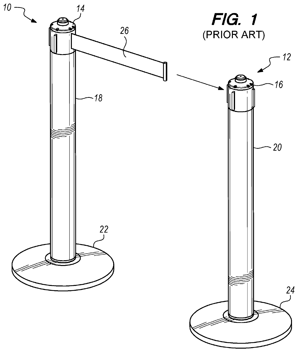
[0029]With reference to FIG. 1 of the drawings, there is provided a perspective diagram of a plurality of prior art interconnectable cap and tape style retractable partitions designated generally by reference numerals 10 and 12, respectively. Partitions 10 and 12 each include respective top caps 14 and 16 affixed or affixable to corresponding upright stanchions 18 and 20, which stanchions are further affixed to corresponding retaining members, in each case shown as weighted bases 22 and 24, respectively. Top cap 14 and 16 each include or incorporate a corresponding retractable tape member that may be removably affixed to a corresponding secondary prior art cap and tape style retractable partition. In FIG. 1, the retractable tape of partition 10 is designated generally by reference numeral 26 and is shown partially extended for connection to secondary retractable partition 12, and more particularly to top cap 16 of secondary retractable partition 12. As those skilled in the art will ...


PUM


Abstract

A non-anchored, self-supporting screen assembly for selective placement by a user on a walking surface. The assembly includes a housing having a first end, a second end, and a sidewall extending therebetween and having an elongate opening. A base independently supports and disposes the housing in an upright position substantially normal to the walking surface during use. A rotatable rod is disposed within the housing and coupled to a trailing edge of a flexible screen. The flexible screen may be coupled to an external attachment point upon extension of the screen through the elongate opening and decoupled upon retraction. A spring is coupled to the rotatable rod to exert a force in a direction opposite a direction of extension of the flexible screen. The flexible screen of an adjacent assembly may be coupled to the assembly to form a screen system.

Description

CROSS-REFERENCE TO RELATED APPLICATIONS[0001]This application is a continuation-in-part of application Ser. No. 15 / 201,665 filed Jul. 5, 2016, the specification of which is incorporated herein by reference in its entirety.TECHNICAL FIELD[0002]This invention relates generally to portable, retractable, and interconnectable, gates and partitions for defining pathways in private and public spaces both indoors and outdoors, guiding and routing persons through such pathways, and inhibiting undesired ingress to and egress from such pathways.BACKGROUND ART[0003]Removable gates, particularly child and pet safety gates, are well known in the art for use in preventing access to residential areas considered unsafe or undesirable for children or pets. Conventional gates characteristically comprise a plurality of cooperating gate sections that are generally horizontally extensible and retractable within specific selected narrow entryways such as between doorjambs, opposed walls, and balustrade up...

Claims


Application Information

Patent Timeline
Patent Type & Authority Patents(United States)
IPC IPC(8): E06B9/08B65H75/44E01F13/02B65H75/48E06B9/06
CPCB65H75/4471B65H75/48E01F13/028E01F13/022B65H2402/63E06B9/0692G09F19/22G09F23/00B65H2402/60
Inventor REINER, ANDREW ERIC
Owner REINER ANDREW ERIC
Why Eureka
Try Eureka