Imaging lens
a technology of imaging lens and focal length, applied in the field of imaging lens, can solve the problems of difficult correction of aberration at the peripheral area, large ratio of total track length to focal length of the overall optical system, and inability to achieve the excellent optical performance of recent years, etc., to achieve low telephoto ratio, high resolution, and balanced low-profile
- Summary
- Abstract
- Description
- Claims
- Application Information
AI Technical Summary
Benefits of technology
Problems solved by technology
Method used
Image

Examples
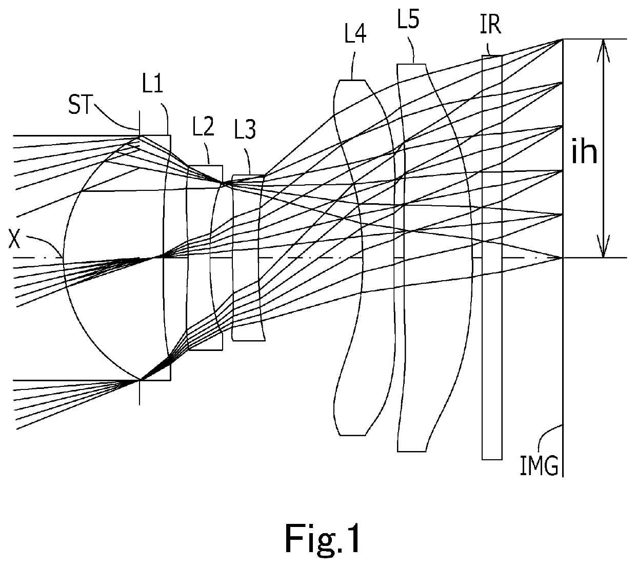
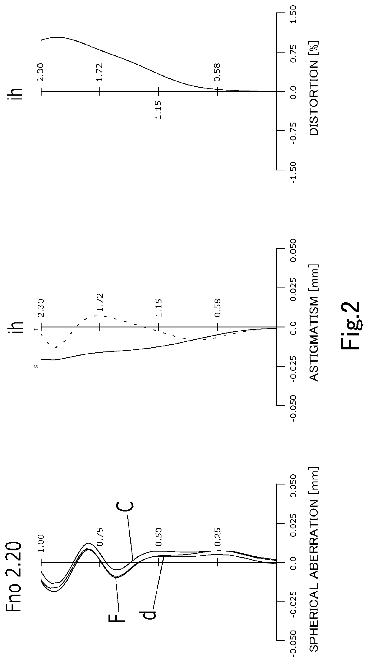
example 1
[0072]
Unit mmf = 5.68Fno = 2.2ω(°) = 21.8ih = 2.30TTL = 5.18Surface DataSurfaceCurvatureSurfaceRefractiveAbbeNumber iRadius rDistance dIndex NdNumber vd(Object)InfinityInfinity 1 (Stop)Infinity−0.7967 2*1.41021.05121.54455.86 (vd1) 3*−57.42810.2587 4*−4.09860.23001.66120.37 (vd2) 5*4.20340.2376 6*5.85390.27001.66120.37 (vd3) 7*6.54911.0994 8*−3.50000.32501.54455.86 (vd4) 9*−196.44740.108510*−94.96420.71951.66120.37 (vd5)11*−8.26100.100012Infinity0.21001.51764.1713Infinity0.6406Image PlaneInfinityConstituent Lens DataLensStart SurfaceFocal LengthComposite Focal Length122.545f345−18.15024−3.1063672.28548−6.55151013.649Aspheric Surface DataSecond SurfaceThird SurfaceFourth SurfaceFifth SurfaceSixth SurfaceSeventh Surfacek0.000000E+000.000000E+000.000000E+000.000000E+00 0.000000E+000.000000E+00A4−1.407693E−03 8.992907E−023.109713E−012.229563E−01−1.633799E−01−5.007662E−02 A6−5.474699E−03 −3.751727E−02 −4.340164E−01 −9.051976E−01 −4.141071E−014.421675E−05A81.157969E−02−1.783428E−02 4.0985...
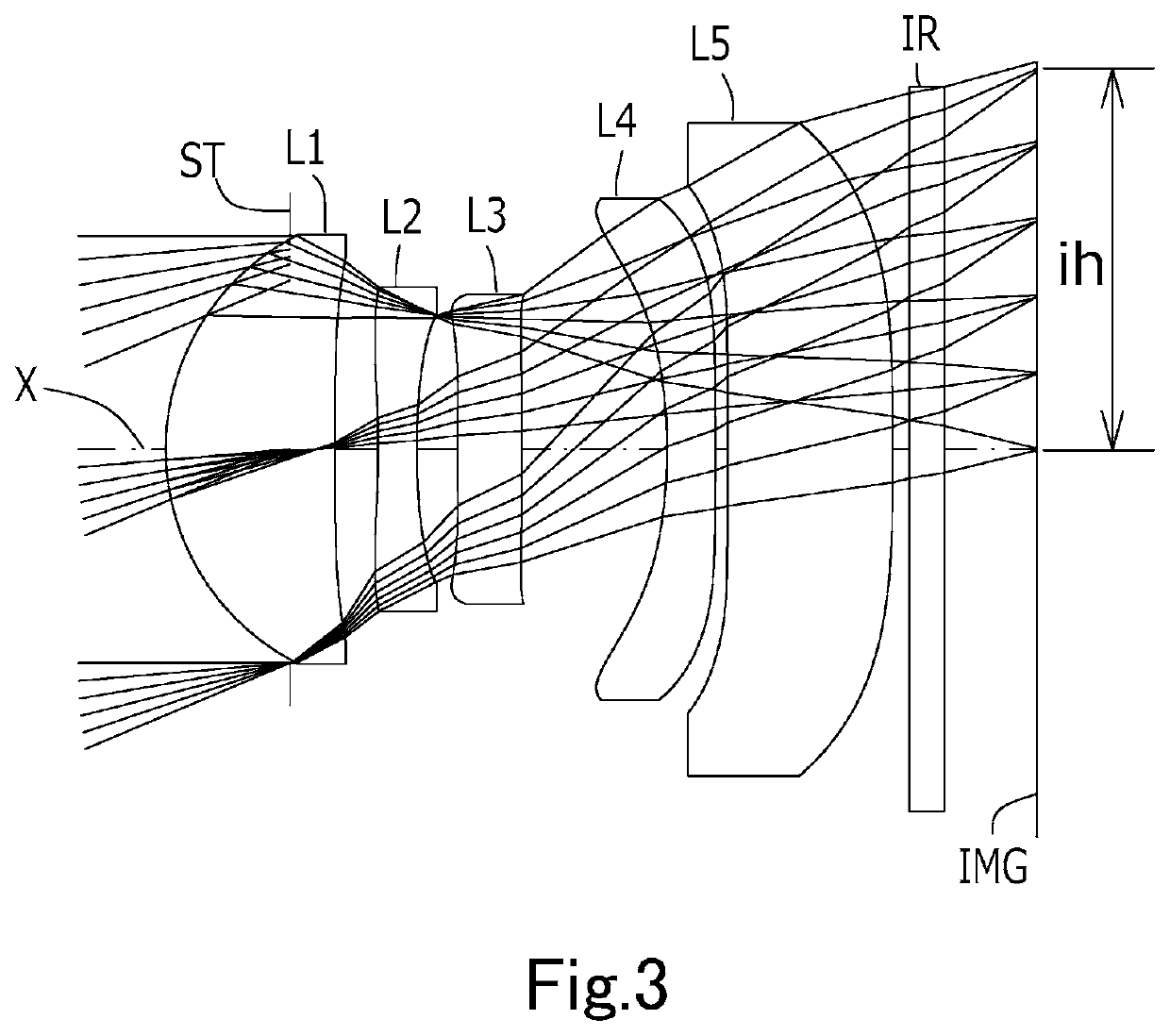
example 2
[0076]
Unit mmf = 5.40Fno = 2.1ω(°) = 22.8ih = 2.30TTL = 5.19Surface DataSurfaceCurvatureSurfaceRefractiveAbbeNumber iRadius rDistance dIndex NdNumber vd(Object)InfinityInfinity 1 (Stop)Infinity−0.7500 2*1.44291.02271.54455.86 (vd1) 3*−70.97710.2606 4*−4.44840.23291.66120.37 (vd2) 5*5.04410.2447 6*13.45740.38761.66120.37 (vd3) 7*54.89640.8788 8*−3.22510.29411.54455.86 (vd4) 9*−15.04310.072710*−55.79180.99641.66120.37 (vd5)11*−50.00000.100012Infinity0.21001.51764.1713Infinity0.5604Image PlaneInfinityConstituent Lens DataLensStart SurfaceFocal LengthComposite Focal Length122.611f345−11.55724−3.5433626.88148−7.609510682.239Aspheric Surface DataSecond SurfaceThird SurfaceFourth SurfaceFifth SurfaceSixth SurfaceSeventh Surfacek0.000000E+000.000000E+000.000000E+000.000000E+00 0.000000E+00 0.000000E+00A4−3.212629E−03 6.519639E−022.437222E−011.968097E−01−1.262989E−01−6.531912E−02A61.399415E−03−1.922983E−02 −3.129261E−01 −8.486969E−01 −5.100122E−01−1.021886E−02A83.036777E−04−1.234310E−02 3.34...
example 3
[0080]
Unit mmf = 5.72Fno = 2.2ω(°) = 21.7ih = 2.30TTL = 5.20Surface DataSurfaceCurvatureSurfaceRefractiveAbbeNumber iRadius rDistance dIndex NdNumber vd(Object)InfinityInfinity 1 (Stop)Infinity−0.7950 2*1.41071.05131.54455.86 (vd1) 3*−71.78840.2596 4*−4.07490.23071.66120.37 (vd2) 5*4.25630.2369 6*5.72040.24861.66120.37 (vd3) 7*6.51101.0976 8*−3.50190.36101.54455.86 (vd4) 9*−39.39960.112110*−27.62660.70871.66120.37 (vd5)11*−7.84180.100012Infinity0.21001.51764.1713Infinity0.6589Image PlaneInfinityConstituent Lens DataLensStart SurfaceFocal LengthComposite Focal Length122.555f345−18.40424−3.1163663.37148−7.08651016.33910Aspheric Surface DataSecond SurfaceThird SurfaceFourth SurfaceFifth SurfaceSixth SurfaceSeventh Surfacek0.000000E+000.000000E+000.000000E+000.000000E+00 0.000000E+000.000000E+00A4−1.281886E−03 8.966316E−023.110655E−012.231940E−01−1.634227E−01−4.991616E−02 A6−5.413496E−03 −3.754461E−02 −4.339445E−01 −9.052611E−01 −4.140807E−013.506411E−04A81.159551E−02−1.783811E−02 4.099...
PUM
 Abstract
Description
Claims
Application Information
 - R&D
- Intellectual Property
- Life Sciences
- Materials
- Tech Scout
- Unparalleled Data Quality
- Higher Quality Content
- 60% Fewer Hallucinations
Browse by: Latest US Patents, China's latest patents, Technical Efficacy Thesaurus, Application Domain, Technology Topic, Popular Technical Reports.
© 2025 PatSnap. All rights reserved.Legal|Privacy policy|Modern Slavery Act Transparency Statement|Sitemap|About US| Contact US: help@patsnap.com