
System and method for controlling utility vehicles

a technology for utility vehicles and control systems, applied in vehicle position/course/altitude control, process and machine control, instruments, etc., can solve problems such as inability to implement, complex systems, and adversely affect the accuracy of sensors, so as to improve the position finding in the surroundings and improve the positon determination

Active Publication Date: 2020-10-27
KNORR BREMSE SYST FUER NUTZFAHRZEUGE GMBH
View PDF12 Cites 0 Cited by
  • Summary
  • Abstract
  • Description
  • Claims
  • Application Information

AI Technical Summary

Benefits of technology

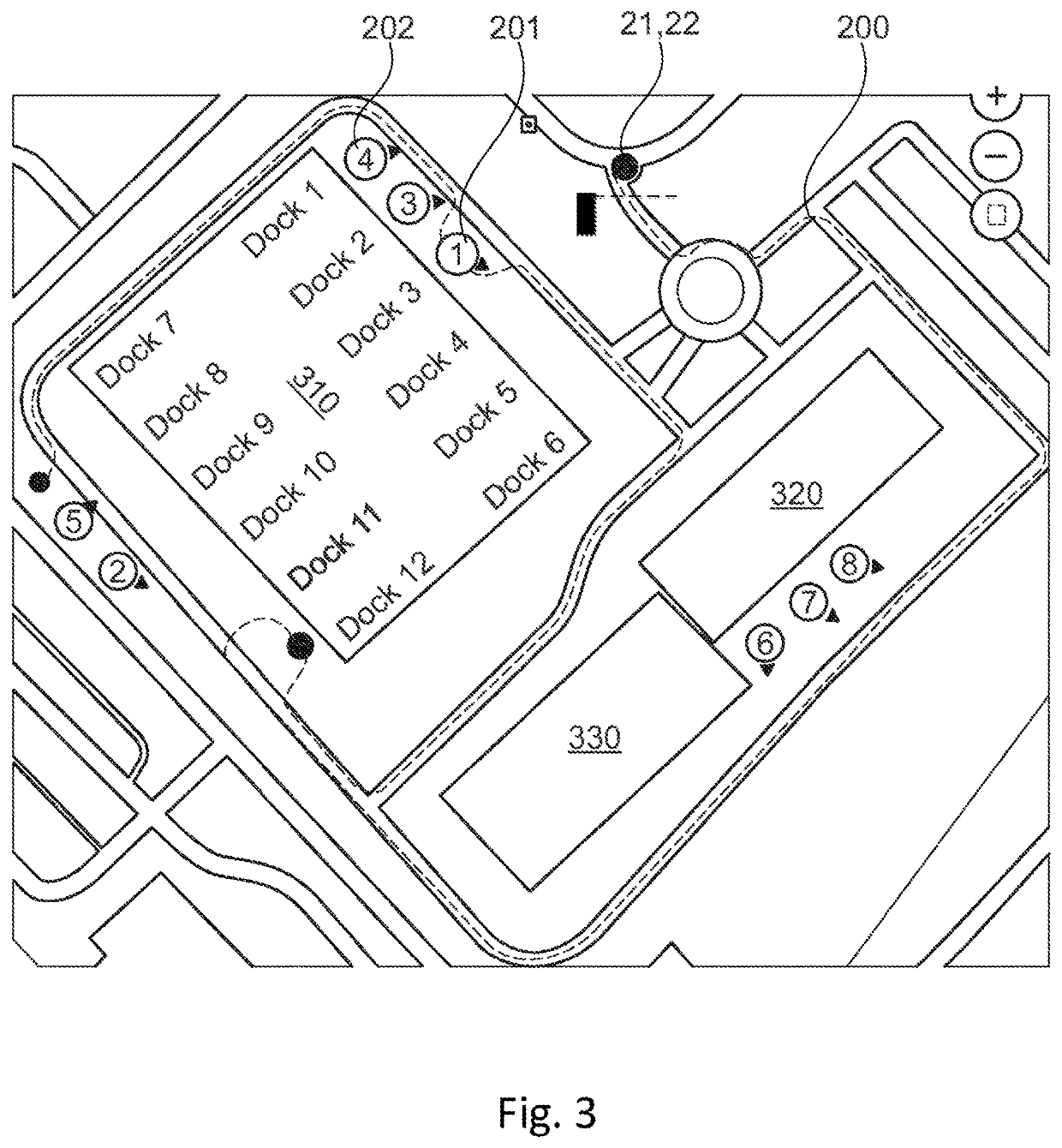
[0008]The identification module can perform mapping, in particular for the identification of objects, specifically the at least one detected object can be mapped onto the cartographic data obtained by the information acquisition module. This mapping can be performed for example such that the cartographic data contain a road area with different buildings that are compared with the objects detected by the detection module in the surroundings of the commercial vehicle. Therefore, explicit identification of the position within the map material acquired from the database is possible. Since the objects in the map material have a known position, the position of the commercial vehicle can therefore be determined or at least the accuracy thereof can be improved.
[0020]Exemplary embodiments for the advantage that improved positon determination is made possible, which is important in particular for safe autonomous movement. This improvement is achieved by the static objects that are downloaded from the database with the cartographic data (map material) and are used to recognize the objects using the ambient sensors. This is accomplished in a simple manner by virtue of the objects from the surroundings being compared against the cartographic data (objects are mapped onto one another).
[0021]Special advantages are afforded by exemplary embodiments in particular in specific, nonstandardized or restricted areas where the positions of static objects in general are known and can be used to further improve the position finding in surroundings of the vehicle.

Problems solved by technology

However, ambient sensors are susceptible to errors and external interference (e.g. on account of poor weather conditions and the like) that adversely affect the accuracy of the sensors.
Such systems are complex, however, and, if no further sensors are available, are not always implementable.

Method used


Image

  • System and method for controlling utility vehicles
  • System and method for controlling utility vehicles
  • System and method for controlling utility vehicles

Examples


Embodiment Construction

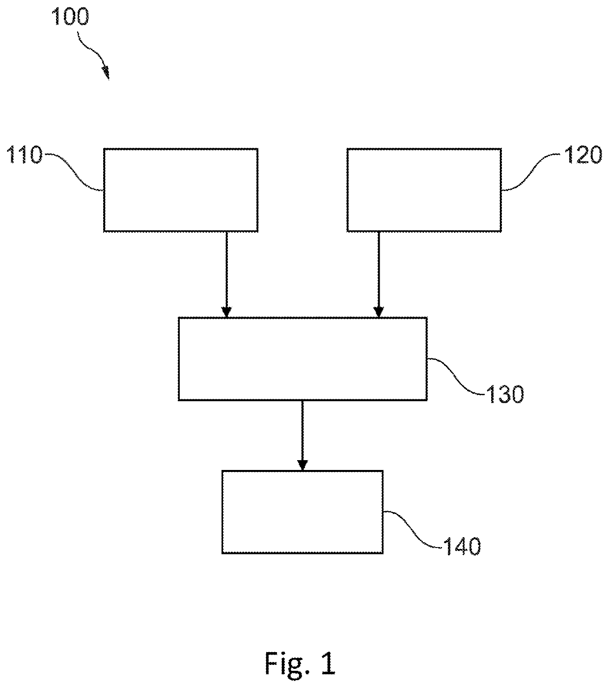
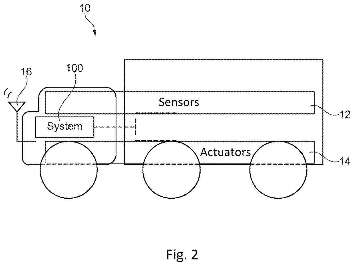
[0027]FIG. 1 shows an exemplary embodiment of a system 100 suitable for controlling commercial vehicles in a restricted area, wherein the commercial vehicle has a sensor unit for detecting objects in surroundings of the commercial vehicle. The system 100 comprises an information acquisition module 110, a detection module 120, an identification module 130 and a movement module 140. The information acquisition module 110 is configured to acquire information about the restricted area from an (external) database, wherein the acquired information has cartographic data for objects in a restricted area and can be obtained by downloading, for example. The detection module 120 is configured to detect at least one object in the surroundings of the vehicle using the sensor unit of the commercial vehicle. The identification module 130 is configured to identify the at least one detected object in the cartographic data. The movement module 140 is configured to allow autonomous movement of the com...


PUM


Abstract

A system for controlling a commercial vehicle in a restricted area, including: an information acquisition module to acquire information from a database about the restricted area, wherein the commercial vehicle includes a sensor unit to detect objects in surroundings of the commercial vehicle, and wherein the acquired information includes cartographic data for objects in the restricted area; a detection module to detect at least one object in the surroundings of the vehicle using the sensor unit of the commercial vehicle; an identification module to identify the at least one detected object in the cartographic data; and a movement module to allow autonomous movement of the commercial vehicle in the restricted area based on the identified objects. Also described are a related commercial vehicle, a method and a computer readable medium.

Description

FIELD OF THE INVENTION[0001]The present invention relates to a system and a method for controlling commercial vehicles in a restricted area and in particular to the use of static objects from a map database for surroundings detection.BACKGROUND INFORMATION[0002]For the autonomous driving of commercial vehicles, it is increasingly important to form suitable environment detection so as thereby to be able to make correct control decisions for the further movement of the commercial vehicle. The environment detection can be achieved for example by a sensor or a combination of different sensors.[0003]However, ambient sensors are susceptible to errors and external interference (e.g. on account of poor weather conditions and the like) that adversely affect the accuracy of the sensors. In order to improve the reliability and accuracy of the object detection, results from different sensors or different algorithms can admittedly be combined with one another so as to obtain confirmation of a de...

Claims


Application Information

Patent Timeline
Patent Type & Authority Patents(United States)
IPC IPC(8): G05D1/02G08G1/16
CPCG08G1/165G08G1/163G05D1/0274G05D2201/0216
Inventor BALOGH, LEVENTENEMETH, HUBAHORVATH, CSABATIHANYI, VIKTORRAPP, TAMAS
Owner KNORR BREMSE SYST FUER NUTZFAHRZEUGE GMBH
Learn More