Beam-mounted supply unit for fastening medical devices to a ceiling

a technology for medical devices and supply units, which is applied in the direction of brake types, mechanical devices, machine supports, etc., can solve the problems of at least making the movement of the chassis along the rail track difficult compared to the operating state of the brake unit deactivation, and achieves compact construction of the brake unit, constant braking torque, and economical and efficient operation.

Active Publication Date: 2020-11-03
DRAGERWERK AG
View PDF15 Cites 0 Cited by
  • Summary
  • Abstract
  • Description
  • Claims
  • Application Information

AI Technical Summary

Benefits of technology

[0015]The special advantage of the present invention is that because of using a spring force or a magnetic force for activating the brake, no auxiliary energy in the form of electric energy or compressed air is needed. Even in case of a power failure, in which a compressed air unit would also fail, the trolley with the support components and / or medical devices located on it is located in a secure operating state. A constant braking torque is especially generated, which, for example, is entirely independent of any fluctuations of the pressure in the compressed air unit. Electric or mechanical energy is only needed for the deactivation of the brake, i.e., for the short time, in which the trolley shall be moved along the rail track. In addition, the present invention makes possible an especially compact construction of the brake unit and thus an economical and efficient operation of a beam-mounted supply unit in a hospital.
[0016]The present invention will be explained in more detail below with reference to the figures based on special exemplary embodiments without limiting the general inventive idea. The various features of novelty which characterize the invention are pointed out with particularity in the claims annexed to and forming a part of this disclosure. For a better understanding of the invention, its operating advantages and specific objects attained by its uses, reference is made to the accompanying drawings and descriptive matter in which preferred embodiments of the invention are illustrated.

Problems solved by technology

Further, a brake unit with at least one braking element is provided, which in the activated state of the brake unit exerts a braking force on the rail track and / or on the chassis, so that a movement of the chassis along the rail track is at least made difficult compared to an operating state with the brake unit deactivated.

Method used


Image

  • Beam-mounted supply unit for fastening medical devices to a ceiling
  • Beam-mounted supply unit for fastening medical devices to a ceiling

Examples


Embodiment Construction

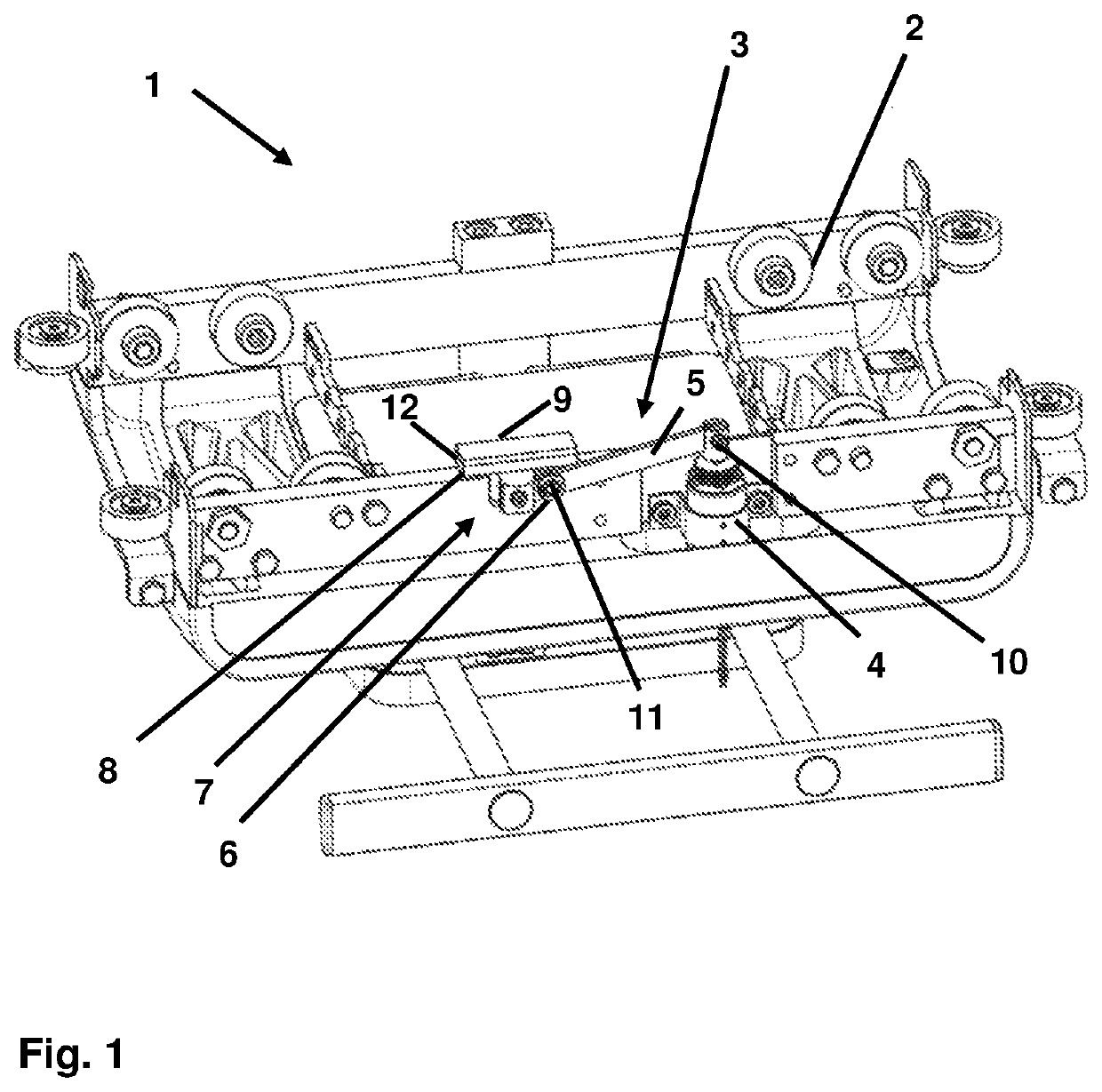
[0020]Referring to the drawings, FIG. 1 shows a trolley 1, which is also called a shuttle, for a beam-mounted supply unit 20, via which device carriers and / or medical devices can be fastened to a ceiling of a treatment room or operating room. The trolley 1 has a chassis 2 with rollers, which are movable along a rail track 13 of the beam-mounted supply unit 20. Such a trolley 1, which can be moved both along a straight line and around correspondingly provided curve elements on the ceiling of a treatment room or operating room, is used at the same time for connecting the supply of gas, power, compressed air and / or data provided in the hospital to the medical devices fastened to the trolley 1. The trolley 1 passes on corresponding media, electric energy and / or data from the hospital infrastructure into corresponding feed lines and couplings, to which the medical devices that are correspondingly needed can then be connected.

[0021]The trolley 1 shown in FIG. 1 has, furthermore, a brake u...


PUM


Abstract

A trolley (1), for a beam-mounted supply unit, for fastening medical devices to a ceiling. The trolley has a chassis (2) which can be meshed with a rail track of the beam-mounted supply unit for moving the trolley (1) along the rail track. A medical device can be fastened to the trolley (1). The trolley has a brake unit (3) with at least one braking element (7), which exerts a braking force on the rail track and / or on the chassis in the activated state of the brake unit (3), so that a movement of the chassis along the rail track is at least made difficult compared to an operating state with the brake unit (3) deactivated. In the activated state of the brake unit (3), the braking force exerted by the braking element (7) on the rail track and / or on the chassis is generated without the aid of electric energy.

Description

CROSS REFERENCE TO RELATED APPLICATIONS[0001]This application is a United States National Phase Application of International Application PCT / EP2017 / 000520, filed Apr. 26, 2017, and claims the benefit of priority under 35 U.S.C. § 119 of German Application 10 2016 005 786.6, filed May 13, 2016, the entire contents of which are incorporated herein by reference.TECHNICAL FIELD[0002]The present invention pertains to a beam-mounted supply unit for fastening medical devices to a ceiling, which supply unit has a rail track and a trolley or a carriage or shuttle, to which at least one medical device can be directly or indirectly fastened. The trolley has a chassis that can be meshed with the rail track for moving the trolley and can be moved along the rail track. Further, a brake unit with at least one braking element is provided, which braking element exerts a braking force on the rail track and / or on the chassis in the activated state of the brake unit, so that a movement of the chassis a...

Claims


Application Information

Patent Timeline
Patent Type & Authority Patents(United States)
IPC IPC(8): A61G12/00F16M13/02F16M11/42F16D63/00F16D121/22F16D121/26F16D125/64
CPCF16M13/027F16D63/008A61G12/004F16M11/425F16M2200/027F16D2125/64F16D2121/26F16D2121/22
Inventor JADER, DHAFIR
Owner DRAGERWERK AG
Why Eureka
Try Eureka