In-line spooling device for compensating fleet angle

a technology of in-line spooling and fleet angle, which is applied in the direction of winding mechanism, hoisting equipment, cranes, etc., can solve the problem of variable fleet angle of the fed cable, and achieve the effect of convenient placement of the respective parts and convenient placemen

Active Publication Date: 2020-11-03
GRANT PRIDECO LP
View PDF24 Cites 0 Cited by
  • Summary
  • Abstract
  • Description
  • Claims
  • Application Information

AI Technical Summary

Benefits of technology

[0013]In a first aspect, this disclosure relates to as spooling device for facilitating spooling of a wire on a drum winch from a feeding point. The spooling device comprises: a frame and a suspension cradle mounted to the frame, wherein the suspension cradle comprises a rotatable wire sheave for receiving the wire and for guiding the wire to a specific location on the drum winch. The suspension cradle with the wire sheave is mounted in a slideable manner to the frame in accordance with a curved path, wherein the curved path is chosen such that a fleet angle of the wire coming from the feeding point is at least partially compensated in order to reduce fringing effects of the wire on the wire sheave during sliding movement of the wire sheave in operational use of the spooling device.
[0014]The effects of such a spooling device are as follows. First of all, the suspension cradle with the wire sheave is mounted in a slideable manner to the frame (for which many implementations are possible) in accordance with a curved path. In addition, this curved path is chosen such that the fleet angle of the wire coming from the feeding point is at least partially compensated for to reduce fringing effects of the wire on the wire sheave during sliding movement of the wire sheave. This partial compensation of the fleet angle means that the angle between the wire and the curved path is kept close to 90 degrees, i.e. the curved path is chosen such that the wire that runs from the feeding point stays substantially perpendicular to the curved path independent of the fleet angle. Another way of saying this is that the wire sheave is kept more in plane with the wire during the reciprocating movement of the suspension cradle.
[0015]Essential to the disclosure is that the wire sheave is mounted in a slideable manner. This is in huge contrast with prior art solutions, which may use a wire sheave that is mounted on a pivotable arm. The advantage of the solution of the current disclosure over that solution is huge, particularly when the feeding point is located further away from the spooling device. In case of a large distance between the feeding point and the spooling device, the pivotable arm or prior devices also needs to be very long (or very complex structures are needed). In the spooling device in accordance with the current disclosure such pivotable arm is completely dispensed with, rendering the solution much more compact and less complex.
[0017]In an embodiment of the spooling device in accordance with the disclosure, the curved path is defined such that the fleet angle is substantially compensated along the full swing of the wire sheave in that the wire remains substantially in plane with the wire sheave during the sliding movement of the wire sheave in operational use of the spooling device. This embodiment further improves the disclosed spooling device by ensuring substantial complete compensation for the fleet angle along the full swing of the suspension cradle and sheave.
[0023]In a third aspect, the disclosure relates to a vessel comprising the crane assembly in accordance with the disclosure. The crane assembly in accordance with the disclosure may be conveniently placed on a floating vessel or a rig.
[0024]In an exemplary embodiment of the vessel, the crane is placed on a deck of the vessel, wherein the drum winch is placed under the deck, and wherein the spooling device is placed under the deck. This embodiment ensures a convenient placement of the respective parts on the vessel.

Problems solved by technology

A general problem with winch systems is that for an efficient spooling, a spooling device or system is needed to facilitate the feeding of the respective wire or cable in a controlled manner.
A known problem, which the spooling device has to overcome or tolerate is that the wire or cable is typically fed from one point, which in combination with the reciprocating movement of the spooling device, results in a variable fleet angle of the cable that is fed to the spooling device.

Method used


Image

  • In-line spooling device for compensating fleet angle
  • In-line spooling device for compensating fleet angle
  • In-line spooling device for compensating fleet angle

Examples


Embodiment Construction

[0035]The following description one embodiment of the spooling device will be discussed and particularly concerning its application to a crane on vessel. However, the disclosure is not limited to these examples and may be applied in any winch application, which makes use of a spooling device.

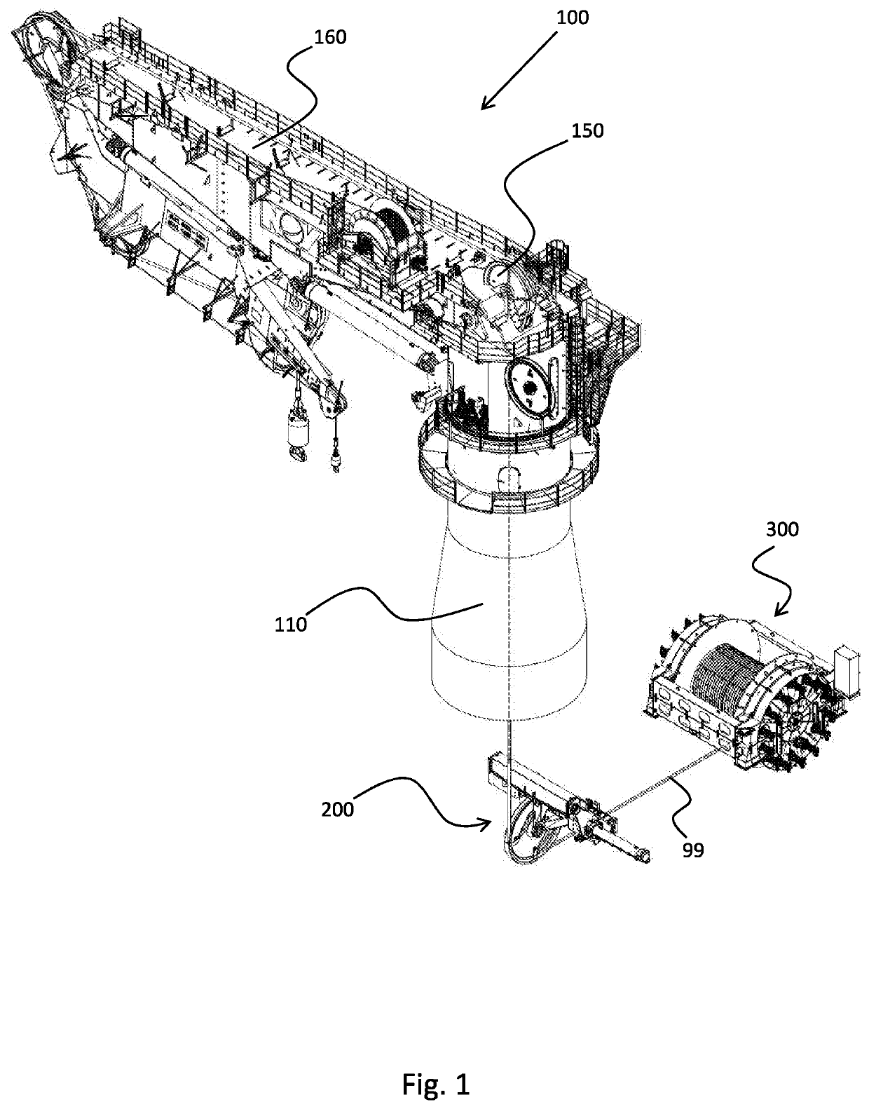
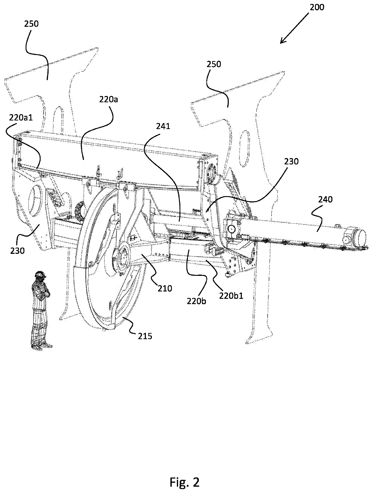
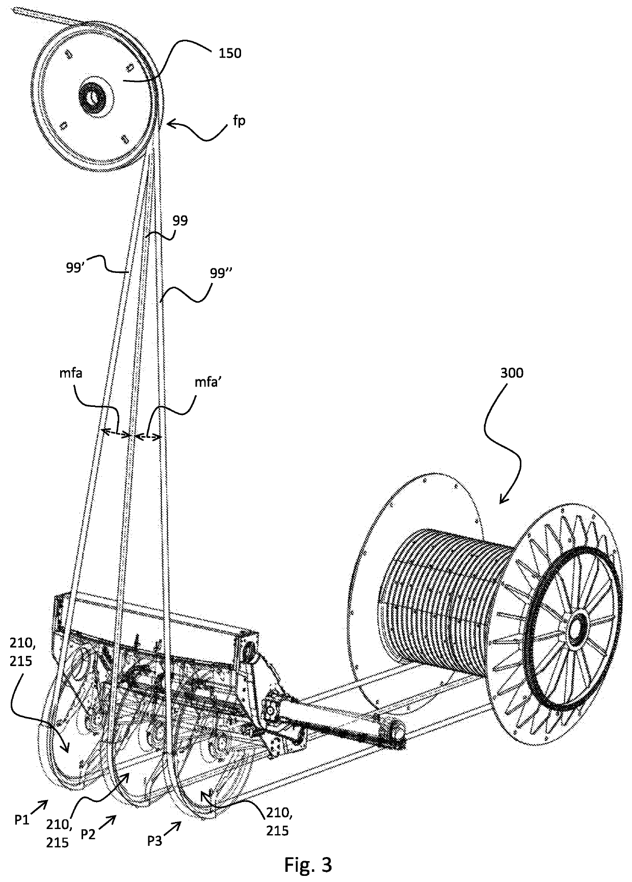
[0036]FIG. 1 discloses an embodiment of a crane assembly. The crane assembly is for use on a vessel (not shown). The crane assembly comprises a crane 100, a spooling device 200 and a drum winch 300 as shown. This embodiment of the crane 100 comprises a crane pedestal 110 with a knuckle boom crane 160 as shown, but the disclosure applies to virtually any type of crane. A wire 99 runs from a crane king sheave 150 on the crane 100 down to the spooling device 200 and then then to drum winch 300. The spooling device 200 in accordance with the disclosure is particularly advantageous when the crane pedestal 110 is long, i.e. when there is a large distance between the crane king sheave 150 and the spool...


PUM


Abstract

A spooling device for facilitating spooling of a wire on a drum winch from a feeding point includes a suspension cradle mounted to the mechanical frame. The suspension cradle supports a rotatable wire sheave or receiving the wire extending form the feeding point and for guiding the wire to a specific location on the drum winch. The suspension cradle having the wire sheave is slideably mounted to the frame in accordance with a curved path. The curved path is configured such that the fleet angle of the wire extending from the feed point is at least partially compensated in order to reduce fringing effects of the wire on the wire sheave during sliding movement of the wire sheave along its curved path.

Description

CROSS REFERENCE TO RELATED APPLICATIONS[0001]This application is a 35 U.S.C. § 371 national stage application of PCT / NO2017 / 050132 filed May 24, 2017 and entitled “In-line Spooling Device for Compensating Fleet Angle”, which claims priority to European Patent Application No. 16172667.4 filed Jun. 2, 2016, each of which is incorporated herein by reference in their entirety for all purposes.STATEMENT REGARDING FEDERALLY SPONSORED RESEARCH OR DEVELOPMENT[0002]Not applicable.FIELD OF THE INVENTION[0003]The invention relates to a spooling device for facilitating spooling of a wire on a drum winch from a feeding point. The invention also relates to a crane assembly comprising such spooling device and to a vessel comprising such crane.BACKGROUND OF THE INVENTION[0004]There are many application fields where drum winches are to be spooled and unspooled in order to effect a translation of a certain object. Examples of such application fields are hoisting applications using cranes both on-shor...

Claims


Application Information

Patent Timeline
Patent Type & Authority Patents(United States)
IPC IPC(8): B66D1/38B66C23/52
CPCB66C23/52B66D1/38B66D1/36
Inventor BORØY, YNGVARJANSEN, LARS-WICHMANNLACERDA, HUGOBJØRGEN, THOMAS
Owner GRANT PRIDECO LP
Why Eureka
Try Eureka