
Self-checkout with three dimensional scanning

a three-dimensional scanning and self-checkout technology, applied in the field of imager-based systems, can solve the problems of insufficient coverage area, inability to select an appropriate 5 foot by 4 foot area for imaging, and the need for expensive and large active illumination systems, so as to improve the assessment of shopping patterns or purchasing decisions

Active Publication Date: 2020-11-03
DATALOGIC USA INC
View PDF28 Cites 9 Cited by
  • Summary
  • Abstract
  • Description
  • Claims
  • Application Information

AI Technical Summary

Benefits of technology

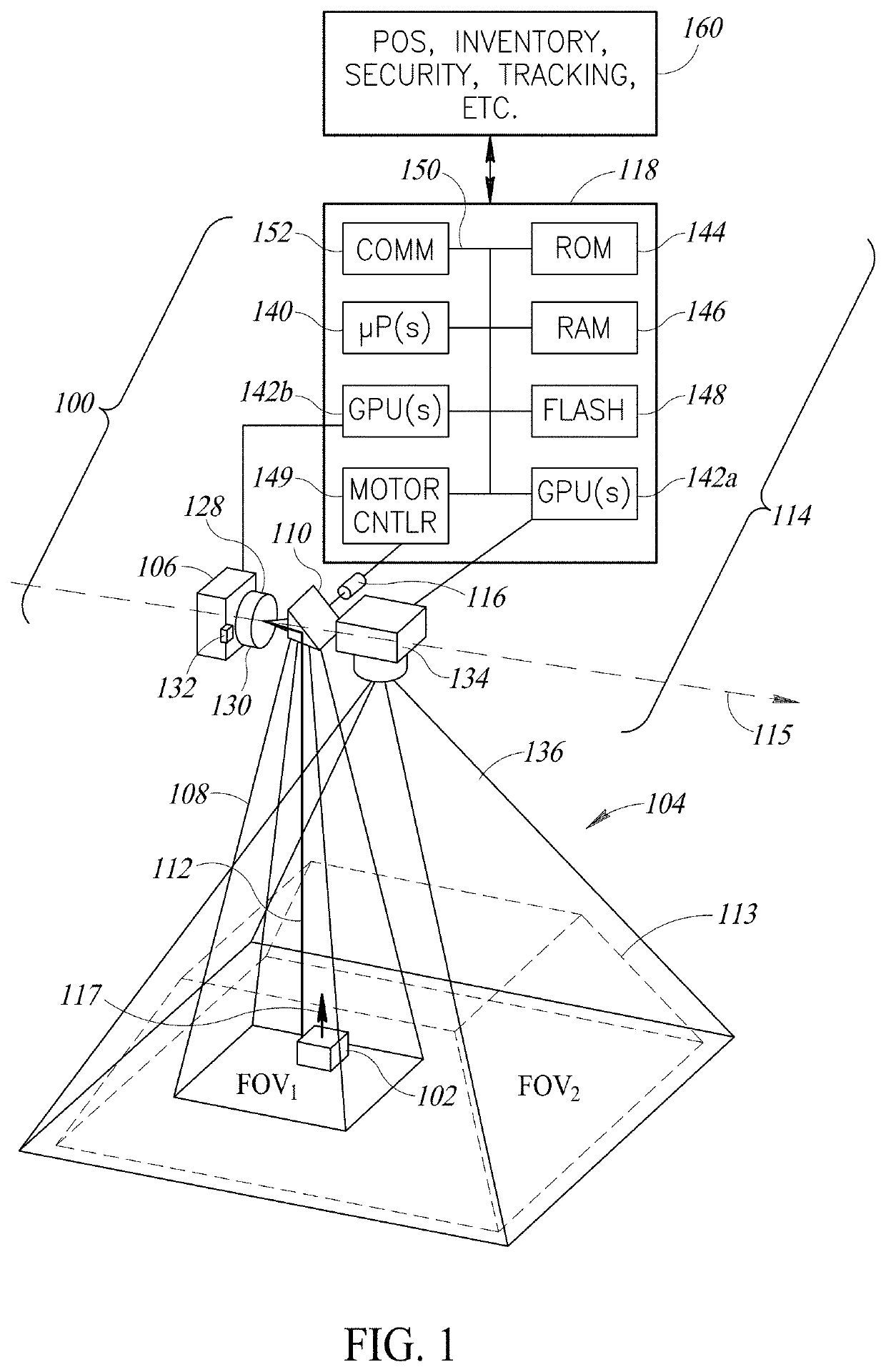
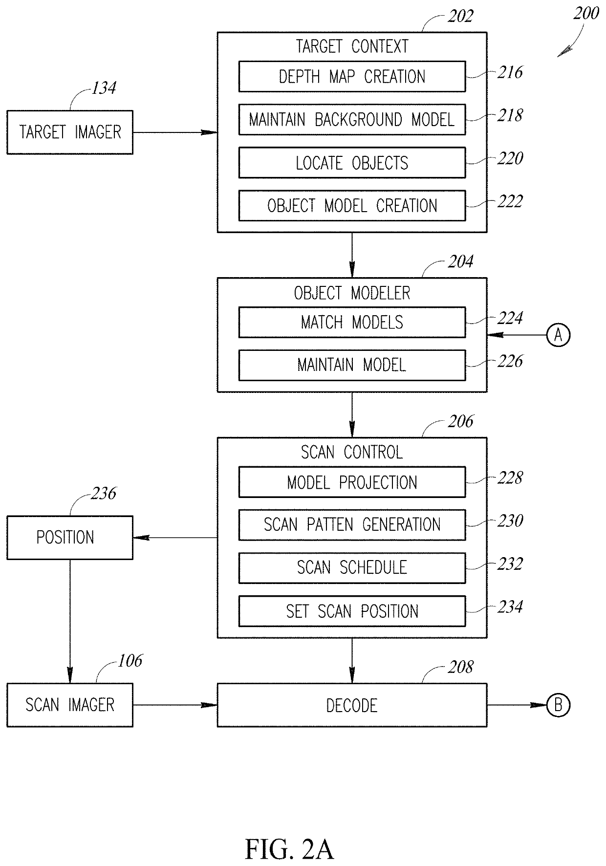
[0005]In at least one implementation, a field of view of a scanning imager or camera is directed or caused to track one or more objects via a steering mirror, for instance a fast steering mirror. A tracking subsystem may include a targeting imager or camera, or some other sensor(s) or transducer(s) that capture data (e.g., 3-dimensional data) that characterizes objects in an environment, for instance a retail environment. In other implementations, images captured by one or more targeting imagers may be used to determine characteristics of objects, which characteristics are used to cause a respective field of view of a scanning imager to track one or more objects. Characteristics may, for example, include distance, dimensions, rotation, images of the object, bounding boxes, scan state, appearance, presence, location, position, speed, and / or direction of travel of the object. Characteristics may also, for example, include physical characteristics of the object and / or packaging, which characteristics allow classifying the object as a certain type of object (e.g., stock keeping unit or SKU, restricted sale type item). The characteristics may be used to generate an object model, which is a collection of properties about an object in the field of view. The steering mirror directs the field of view of the relatively higher resolution scanning imager with a relatively narrow field of view to track an object, for example an object spotted in a wider field of view of one or more targeting imagers, and / or an object that is in motion. For moving objects, relative motion between the object and the field of view of the higher resolution imager is reduced or eliminated.
[0007]This approach can be employed, for example, to advantageously detect objects or items in a shopping cart, shopping basket, a customer's hands, or elsewhere at a checkout station or counter. Detected objects or items may be identified and added to a transaction list to implement a transaction process. Further, this approach can be employed, for example, to recognize individuals (e.g., customers). This approach can be employed, for example, to advantageously monitor shopping at a checkout station or counter of a retail environment, or at other locations. For example, this approach can be employed, for example, to monitor or track the selection of items or objects from shelves and placement into a shopping cart or shopping basket in aisles of a retail environment, allowing better assessment of shopping patterns or purchasing decisions or, conversely, detection of shoplifting.

Problems solved by technology

For example, if the application is monitoring or tracking objects or items at a checkout station or counter of, for instance a grocery store (e.g., on a conveyor belt at the checkout station or counter, and / or in the shopping cart), this area of coverage is not sufficient.
In particular, a position of a shopping cart at a checkout station or counter can vary substantially from one checkout transaction to another, or even during a single checkout transaction, making selection of an appropriate 5 foot by 4 foot area for imaging virtually impossible.
For moving objects, sharp image capture typically requires very fast shutter speeds, which can be impossible using ambient light, leading to the need for expensive and large active illumination systems.
Active illumination can interfere with other opto-electronic components of a system or device, and may present an annoyance to human operators.

Method used


Image

  • Self-checkout with three dimensional scanning
  • Self-checkout with three dimensional scanning
  • Self-checkout with three dimensional scanning

Examples


Embodiment Construction

[0037]In the following description, certain specific details are set forth in order to provide a thorough understanding of various disclosed implementations. However, one skilled in the relevant art will recognize that implementations may be practiced without one or more of these specific details, or with other methods, components, materials, etc. In other instances, well-known structures associated with computer systems, server computers, and / or communications networks have not been shown or described in detail to avoid unnecessarily obscuring descriptions of the implementations.

[0038]Unless the context requires otherwise, throughout the specification and claims that follow, the word “comprising” is synonymous with “including,” and is inclusive or open-ended (i.e., does not exclude additional, unrecited elements or method acts).

[0039]Reference throughout this specification to “one implementation” or “an implementation” means that a particular feature, structure or characteristic de...


PUM


Abstract

Systems and methods for providing self-checkout systems that utilize a scanning imager or camera which includes a selectively steerable field of view. A tracking subsystem may include a targeting imager or camera that captures data (e.g., 3-dimensional data) that characterizes objects in an environment, for instance a retail environment. Images captured by one or more targeting imagers may be used to determine characteristics of objects. The characteristics may be used to generate an object model, which is a collection of properties about an object in the field of view. The tracking subsystem directs the field of view of the relatively higher resolution scanning imager with a relatively narrow field of view to track one or more objects so that images of the objects may be captured. The images are processed to identify the identification of the objects so that the objects may be added to a transaction list to complete a purchase process.

Description

BACKGROUNDTechnical Field[0001]The present disclosure relates to imager based systems, for example image-based systems that automatically detect, monitor and track objects in an environment, for instance in a retail store.Description of the Related Art[0002]Many applications would benefit by automated detection, monitoring or tracking of objects in the respective environment. For example, retail, warehouse, baggage sorting, parcel sorting, or gaming casino environments may benefit by automated detection, monitoring or tracking of objects using image-based techniques.[0003]In many applications or environments, objects to be monitored or tracked are moving or in transit. For example, a retail environment (e.g., grocery or convenience store) may employ ceiling mounted cameras used for detection of items in shopping carts. Such cameras must be capable of capturing relatively high-resolution images in order to discern the specific objects or items. In particular, machine vision algorithm...

Claims


Application Information

Patent Timeline
Patent Type & Authority Patents(United States)
IPC IPC(8): G06Q20/20G06K9/32G07G1/00G06K9/52G06Q20/18G06V10/42
CPCG07G1/0063G06Q20/18G06K9/52G06K9/3208G06Q20/208G06V10/242G06V10/42
Inventor OLMSTEAD, BRYANMCCORMACK, KENGAO, WENLIANG
Owner DATALOGIC USA INC
Learn More