Multi-lens camera module

a camera module and lens technology, applied in the field of multi-lens camera modules, can solve the problems of limited camera module size, lower performance and higher power consumption of ois and af vcm, and achieve the effects of reducing magnetic interference, reducing magnetic interference, and simplifying structural design

Active Publication Date: 2020-11-03
POWERGATE OPTICAL INC
View PDF6 Cites 1 Cited by
  • Summary
  • Abstract
  • Description
  • Claims
  • Application Information

AI Technical Summary

Benefits of technology

[0005]The invention relates to a multi-lens camera module which can simply decrease magnetic interference without the need of complicate structural design. No matter the camera module is equipped with traditional VCM AF or OIS or both, the invention uses the characteristic configuration of the magnetic field of lens driving device to reduce magnetic interference between the magnetic fields of two adjacent lens modules. Such that, the unstable offsets of optical axes of two adjacent lens modules due to the magnetic interference can be reduced, the stability when adjusting the lens module can be increased, the distance between two adjacent lens modules can be shortened, the space required for furnishing the multi-lens camera module inside the smart phone can be efficiently configured, and better magnetic interference performance at the same power consumption can be obtained.

Problems solved by technology

In the slim design of smart phones, the internal Central Processing Unit (CPU), memory and battery module have occupied most of the space, therefore the size of camera module is limited.
Although the magnetic interference is reduced with smaller driving magnets, however, the pushing (driving) forces, especially the horizontal pushing forces, are also reduced, which inevitably results in lower performances and higher power consumptions of OIS and AF VCM.

Method used


Image

  • Multi-lens camera module
  • Multi-lens camera module
  • Multi-lens camera module

Examples


Embodiment Construction

[0063]The invention disclosed herein is directed to a multi-lens camera module. In the following description, numerous details are set forth in order to provide a thorough understanding of the present invention. It will be appreciated by one skilled in the art that variations of these specific details are possible while still achieving the results of the present invention. In other instance, well-known components are not described in detail in order not to unnecessarily obscure the present invention.

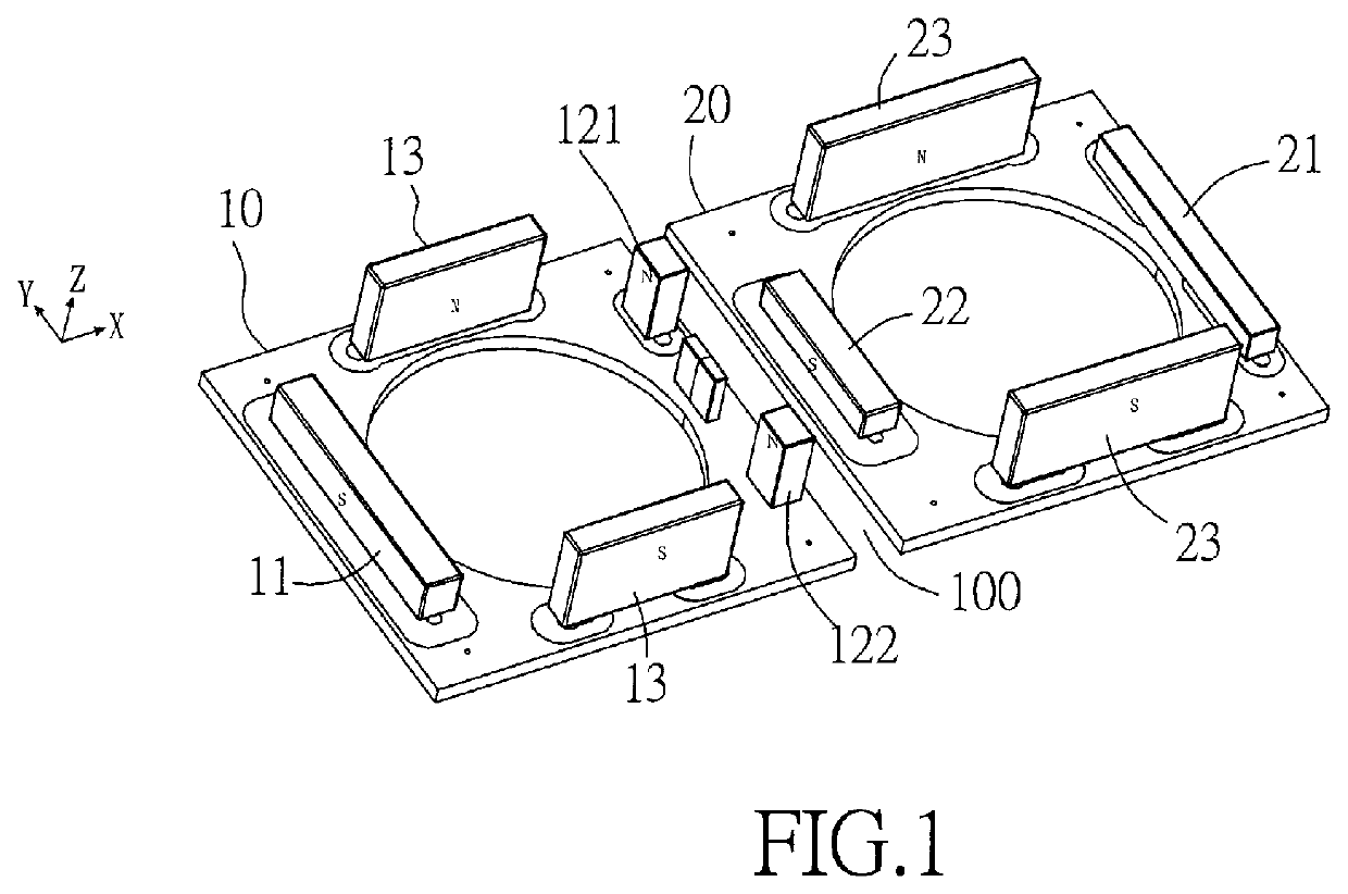
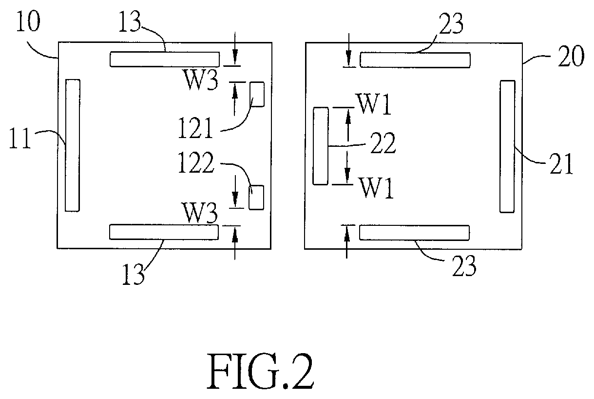
[0064]The lens module with OIS system usually includes an electromagnetic driving system having either four corner-typed driving magnets or four side-typed driving magnets. These driving magnets are mounted on a frame which is suspended above a base by four suspension wires. For a multi-lens camera module having multiple lens modules, the adjacent two lens modules are close to each other, and the driving magnets in the two lens modules will result in magnetic interference with each other...


PUM


Abstract

A multi-lens camera module comprises at least two lens modules located side-by-side. Each lens module can be a voice coil motor (VCM) lens module having an auto-focusing (AF) or / and an optical image stabilizer (OIS) functions. The surface where two lens modules are adjacent with is called the neighbouring surface. A projection view on the neighbouring surface of a plurality of secondary driving magnets of these lens modules located at two sides of the neighbouring surface includes at least one secondary driving magnet which has two opposite edges with unequal length; in addition, shapes of these two opposite edges include at least one of the following: slope, arc and straight line. These secondary driving magnets are arranged across the neighbouring surface in a staggered manner.

Description

BACKGROUND OF INVENTION1. Field of the Invention[0001]The invention is referring to a multi-lens camera module, especially to a multi-lens camera module having Auto Focusing (AF) Voice Coil Motor (VCM) or Optical Image Stabilizer (OIS) for electronic devices.2. Description of the Prior Art[0002]In the slim design of smart phones, the internal Central Processing Unit (CPU), memory and battery module have occupied most of the space, therefore the size of camera module is limited. Another trend of design for smart phones of various brands is to furnish multi-lens camera module inside the smart phone, and moreover, camera module equipped with OIS has become a standard equipment in flagship smart phones.[0003]OIS is the abbreviation of Optical Image Stabilizer system, which uses a gyroscope to sense the directions and offsets of shakings, and the system analyses and predicts the image deviations based on the data sensed by the gyroscope. And then, the system controls the lens to make a c...

Claims


Application Information

Patent Timeline
Patent Type & Authority Patents(United States)
IPC IPC(8): H04N5/225G03B21/43G02B7/02G03B21/14
CPCG02B7/021G03B21/145G03B21/43G03B21/142H04N5/2254H04M1/0264H04N23/50H04N23/54H04N23/55H04N23/57G02B7/08G02B27/646H02K41/0356H04N23/45H04N23/687
Inventor HUANG, YING CHUNCHEN, YU CHIACHUANG, HSIEH JENHO, TE PAO
Owner POWERGATE OPTICAL INC
Why Eureka
Try Eureka